Cryogenic storage device

a storage device and cryogenic technology, applied in the field of cryogenic storage devices, can solve the problems of sample material loss, sample melting, and overfilling with liquid nitrogen, and achieve the effect of avoiding unnecessarily high power consumption and coolant consumption

Inactive Publication Date: 2015-01-06
FRAUNHOFER GESELLSCHAFT ZUR FOERDERUNG DER ANGEWANDTEN FORSCHUNG EV
View PDF18 Cites 1 Cited by
  • Summary
  • Abstract
  • Description
  • Claims
  • Application Information

AI Technical Summary

Benefits of technology

[0033]Depending on the detected operating state of the cryogenic storage device, different measures may be necessary for protecting the samples. Associated therewith, different residence times of the sample carrier device in the intermediate storage container can be expected. Short residence times of the sample carrier device in the intermediate storage container require temperatures that are not as low as the temperatures for long residence times. Therefore, for a short

Problems solved by technology

Such mistakes can lead to an irretrievable loss of the sample material.
When refilling the cryogenic container with liquid nitrogen, however, an overfilling with liquid nitrogen may occur under some circumstances.
In this case, the samples in the racks arranged above the liquid reservoir may come into contact with the liquid nitrogen and may thus be destroyed.
Particularly at the aforementioned low

Method used


Image

  • Cryogenic storage device
  • Cryogenic storage device
  • Cryogenic storage device

Examples


Embodiment Construction

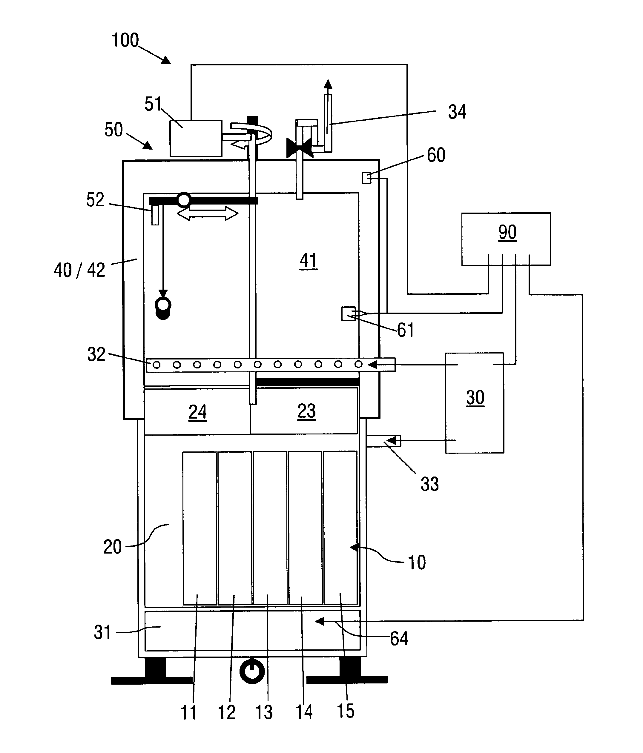
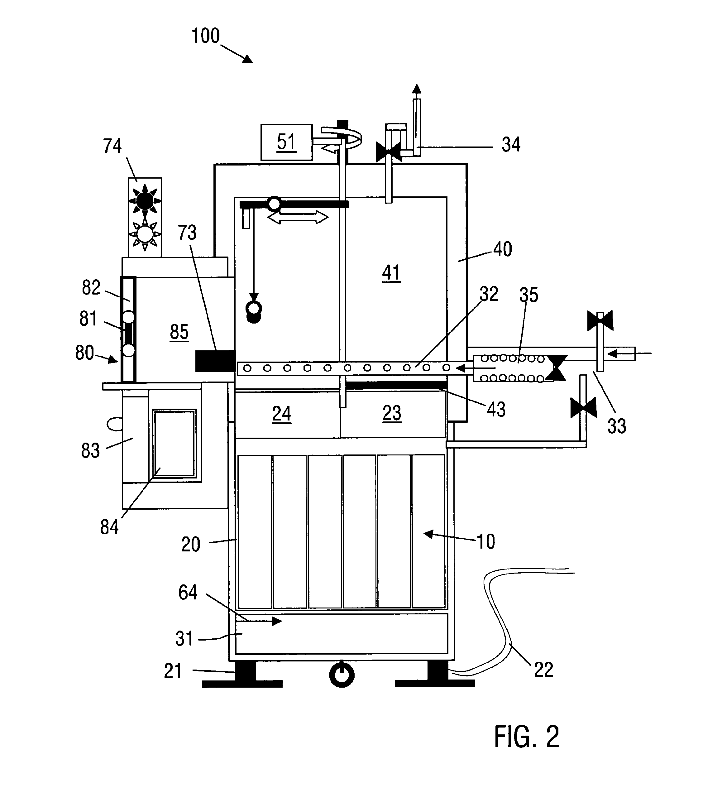
[0045]The sectional view in FIG. 1 shows a cryogenic storage device 100 with a cryogenic container 20, comprising a cylindrical cryogenic tank with a wall thermally insulated by vacuum. A sample carrier device 10, comprising a plurality of carrier parts 11 to 15, is accommodated in the cryogenic container. A liquid bath 31 containing liquid nitrogen is arranged below the sample carrier device 10, so that the sample carrier device 10 in the gas phase is located above the liquid nitrogen bath. The liquid bath is supplied from a cooling device 30 by means of a refilling line 33 for liquid nitrogen. A filling lever sensor 64 serves for monitoring the quantity of nitrogen in the cryogenic container 20.

[0046]The cryogenic container 20 has at its upper end an opening which is closed by thermally insulated cover parts 23 and 24. An intermediate storage container 40 is arranged on the cryogenic container 20. The intermediate storage container 40 is adapted as a substantially cylindrical stor...


PUM


Abstract

The invention relates to a cryogenic storage device and to a method for operating a cryogenic storage device, particularly for cryogenic storage of biological samples, comprising a sample carrying device that is set up to accommodate samples, a cryogenic container that is set up to accommodate the sample carrying device, a container cooling device with which the cryogenic container can be cooled, an intermediate storage container that is set up for intermediate storage of the sample carrying device, a transport device with which the sample carrying device can be moved between the cryogenic container and the intermediate storage container and a sensor device with which at least one operating parameter of the cryogenic storage device can be registered. The transport device is set up to be activated in dependence on an output signal from the sensor device upon registering a predetermined operating condition of the cryogenic storage device, so that the sample carrying device is moved from the cryogenic container to the intermediate storage container. Additionally or alternatively, an intermediate storage cooling device that is set up for cooling the intermediate storage container can be activated in dependence on an output signal of the sensor device.

Description

BACKGROUND OF THE INVENTION[0001]The invention relates to a cryogenic storage device, in particular for the cryogenic storage of biological samples, and to a method for operating a cryogenic storage device.[0002]It is known in biology, biotechnology, pharmacology and medicine to store samples of biological material in a frozen state. In order to maintain the vitality of the samples over a relatively long period of time, very low temperatures are required for this, for example, the temperature of liquid nitrogen or of liquid nitrogen vapor. A recrystallization in the samples, which could result in the sample material being destroyed, can be avoided for months and years at such low temperatures. Such cryogenic samples are usually stored in cryogenic containers which are usually vacuum-insulated, known as cryogenic tanks. Such cryogenic tanks can be cooled for example by liquid nitrogen which is located in a liquid bath at the bottom of the cryogenic tank. The samples are often stored ...

Claims


Application Information

Patent Timeline
IPC IPC(8): F25D13/06F17C3/10F25D25/00F25D11/00A01N1/02G01N1/42G01N35/00
CPCA01N1/0252G01N1/42G01N2035/00435F25B2700/04F25D3/102F25D3/11F25D29/001F25D2600/02F25D2700/12F25D2700/16
Inventor ZIMMERMANN, HEIKOSCHOEN, UWEFUHR, GUENTER R.LEUTHOLD, DIRKBELKE, MARIANNE
Owner FRAUNHOFER GESELLSCHAFT ZUR FOERDERUNG DER ANGEWANDTEN FORSCHUNG EV
Why Eureka
Try Eureka