Phase continuity technique for frequency synthesis

a phase continuity and frequency synthesis technology, applied in the field of phase discontinuity mitigation technique within a phased, can solve the problems of interference with transmissions on other channels, spectral emission masks (sems), and frequency of carrier signals that may give rise to spurious signal emissions

Inactive Publication Date: 2018-02-13
QUALCOMM INC
View PDF12 Cites 3 Cited by
  • Summary
  • Abstract
  • Description
  • Claims
  • Application Information

AI Technical Summary

Problems solved by technology

Up-converting the modulating signal from the baseband to the frequency of the carrier signal may give rise to spurious signal emissions including for example, but not limited to, residual sideband (RSB) signals and intermodulation (IM) products (e.g., primary and second 4FMOD signals).
In particular, when RB allocation is narrow (e.g., one RB), the operation of a conventional transmit path may generate spectral emission masks (SEMs) that fall outside of the frequency band allocated to a UE and interfere with transmissions on other channels.
However, adoption of AMPR parameters may reduce the output power of the UE and thus limit the UE's coverage area.

Method used


Image

  • Phase continuity technique for frequency synthesis
  • Phase continuity technique for frequency synthesis
  • Phase continuity technique for frequency synthesis

Examples


Embodiment Construction

[0037]While a number of aspects are described herein, these aspects are presented by way of example only, and are not intended to limit the scope of protection. The apparatuses and methods described herein may be embodied in a variety of other forms. Furthermore, various omissions, substitutions, and changes in the form of the example apparatuses and methods described herein may be made without departing from the scope of protection.

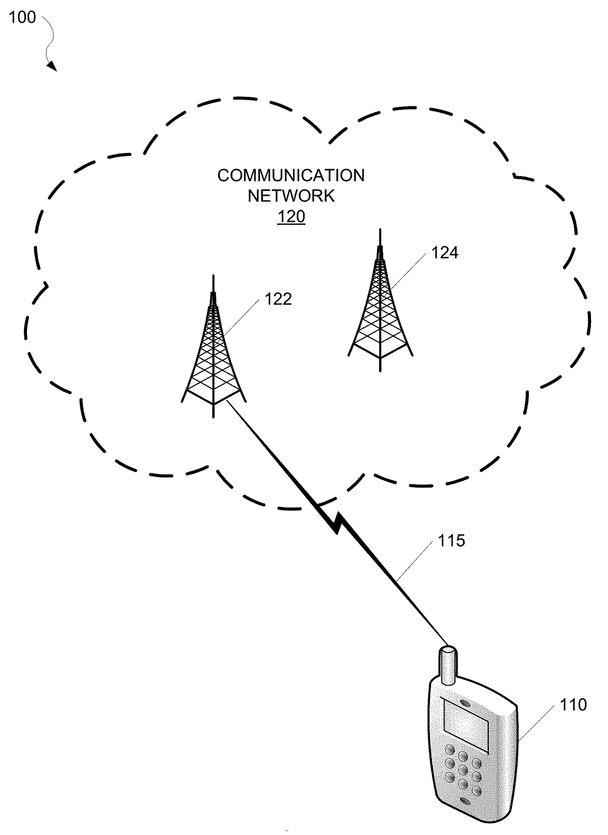
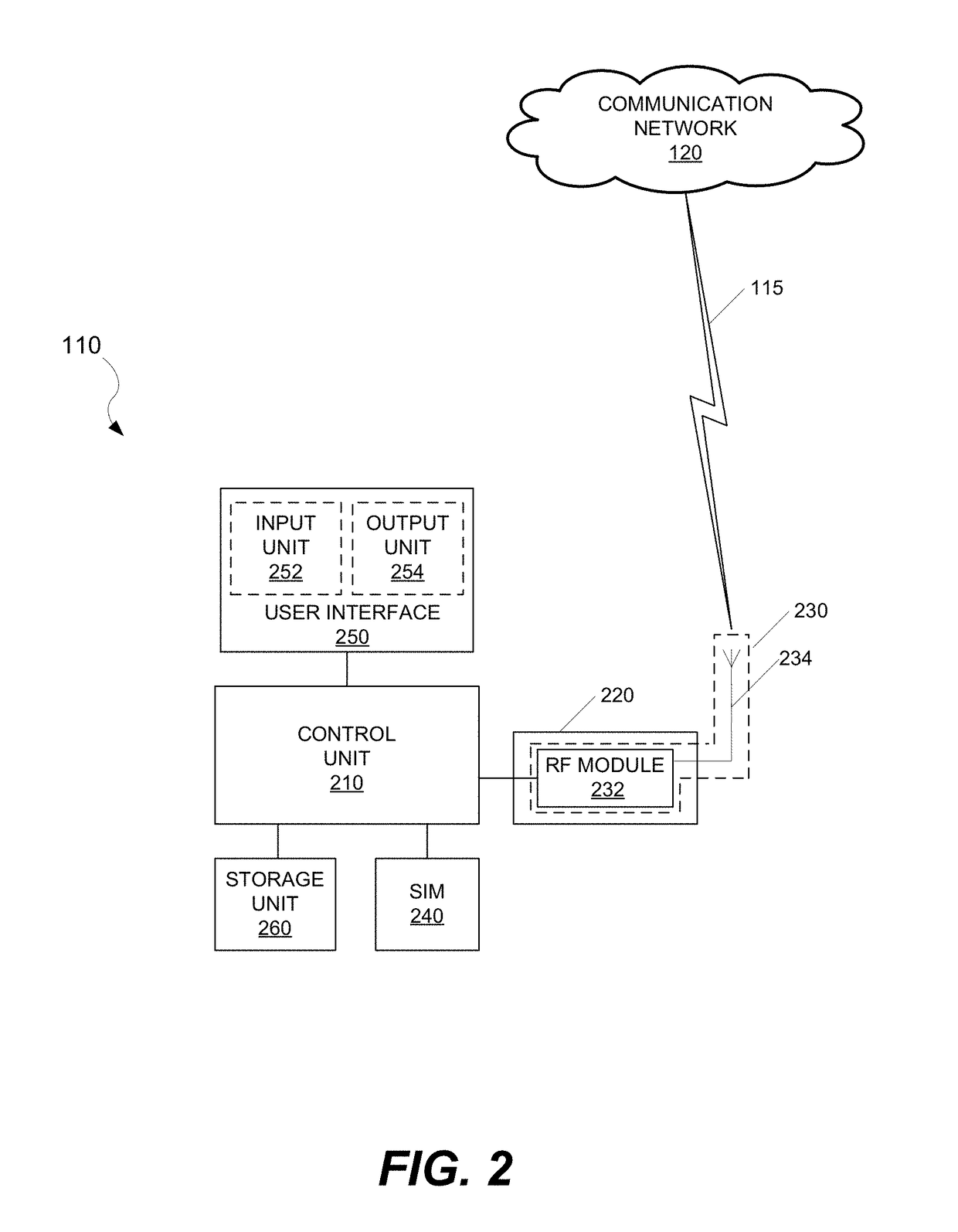
[0038]A phase lock loop (PLL) (e.g., PLL circuit) is often an important component of a device that is designed to operate in a wireless communication system. The PLL forces the voltage controlled oscillator (VCO) to replicate and track a reference frequency and phase at an input when the PLL is in lock configuration. When locked, the frequencies of the input (e.g., at a phase detector) and output (e.g., at a VCO) are tracked exactly (e.g., input frequency=output frequency). A phase offset, however, may exist between the input and output.

[0039]A PLL refer...


PUM


Abstract

A phase discontinuity mitigation implementation within a phased lock loop (PLL) improves throughput of a radio access technology. The throughput is improved by maintaining a phase of the PLL while powering off some devices of the PLL, such as a local oscillator (LO) frequency divider. In one instance, when the PLL is powered down, one or more portions of a delta sigma modulator for the PLL are clocked with a reference clock for the PLL. This implementation maintains phase continuity when the first phase lock loop turns back on.

Description

CROSS-REFERENCE TO RELATED APPLICATION[0001]The present application claims the benefit of U.S. Provisional Patent Application No. 62 / 340,415, filed on May 23, 2016, and titled “PHASE CONTINUITY TECHNIQUE FOR FREQUENCY SYNTHESIS,” the disclosure of which is expressly incorporated by reference herein in its entirety.BACKGROUNDTechnical Field[0002]The present disclosure relates generally to wireless communication systems, and more specifically to a phase discontinuity mitigation technique within a phased lock loop.Related Art[0003]In a long term evolution (LTE) communication network, uplink radio resources may be allocated dynamically to user equipment (UE) based on different applications, data rates, and quality of service (QoS) specifications. Specifically, a UE in an LTE communication network may be allocated varying numbers of resource blocks (RBs) for uplink transmissions from the UE. Each RB may extend over one slot period (e.g., 0.5 milliseconds (ms)) in the time domain while oc...

Claims


Application Information

Patent Timeline
Patent Type & Authority Patents(United States)
IPC IPC(8): H03D3/24H04L7/033H04L29/06H03L7/14H03L7/197H04L5/14H04W84/04
CPCH04L5/14H04L69/28H03L7/1976H04L7/033H03L7/14H03L7/143H03L2207/08H04W84/042
Inventor ZANUSO, MARCOELBADRY, MOHAMMADHUNG, TSAI-PISRIDHARA, RAVIGATTA, FRANCESCOZHUANG, JINGCHENG
Owner QUALCOMM INC
Why Eureka
Try Eureka