
Low latency handover between wireless communication networks using different radio access technologies

a wireless communication network and radio access technology, applied in wireless communication services, wireless communication services, electrical equipment, etc., can solve the problems of user experience a large break, unacceptably high call handover latency,

Active Publication Date: 2009-08-13
CELLO PARTNERSHIP DBA VERIZON WIRELESS
View PDF6 Cites 80 Cited by
  • Summary
  • Abstract
  • Description
  • Claims
  • Application Information

AI Technical Summary

Benefits of technology

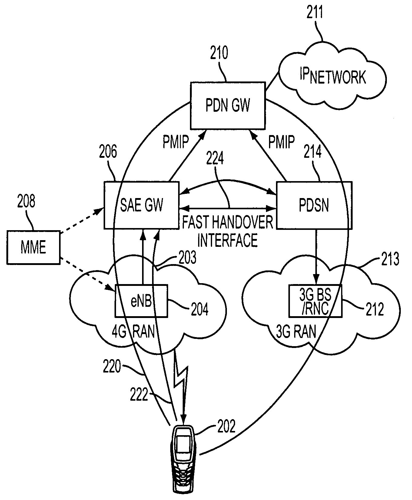
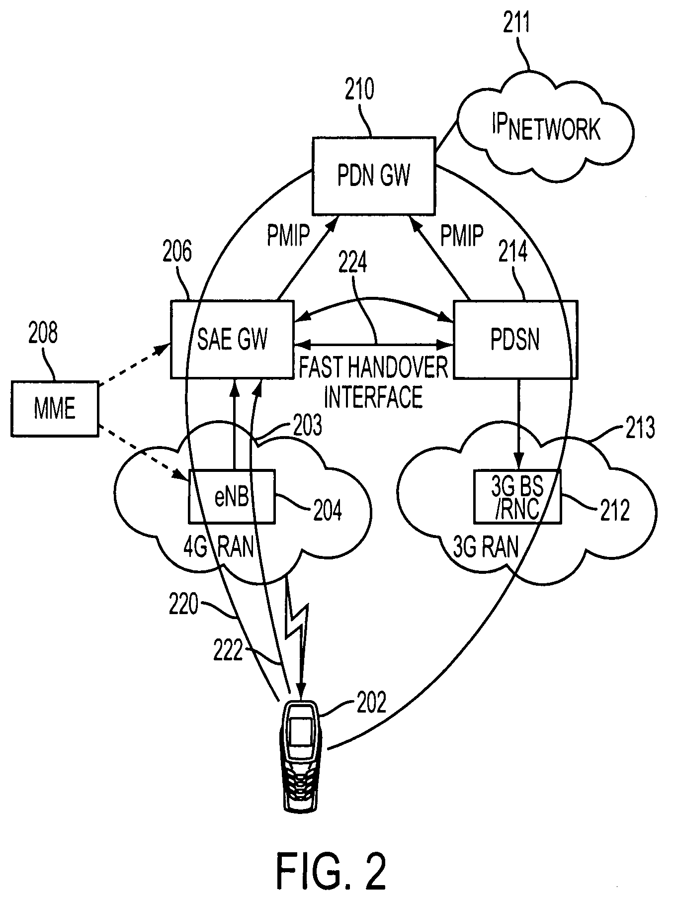
[0013]A handover interface is provided between the first access gateway and the second access gateway for enabling the MS to switch between the first radio access network and the second radio access network with minimum latency.
[0023]Further, the handover interface may provide a bearer path between the first access gateway and the second access gateway. This bearer path may enable the MS to continue a call performed over the first radio access network when the MS switches from the first radio access network to the second radio access network.

Problems solved by technology

In addition, if the MS 10 is not capable of keeping both radio access technologies active at the same time, it needs to setup new radio access resources and link layer related information using the new radio access mechanism.
In existing IP-based wireless networks, when transitioning between network technologies, the call handover latency is unacceptably high for real-time traffic applications such as Voice over IP (VoIP) or streaming video.
Due to the high call handover latency, a user may experience a large break in a video or a voice conversation, or a call may be dropped.

Method used


Image

  • Low latency handover between wireless communication networks using different radio access technologies
  • Low latency handover between wireless communication networks using different radio access technologies
  • Low latency handover between wireless communication networks using different radio access technologies

Examples


Embodiment Construction

[0037]In the following detailed description, numerous specific details are set forth by way of examples in order to provide a thorough understanding of the relevant teachings. However, it should be apparent to those skilled in the art that the present teachings may be practiced without such details. In other instances, well known methods, procedures, components, and circuitry have been described at a relatively high-level, without detail, in order to avoid unnecessarily obscuring aspects of the present teachings.

[0038]The present disclosure will be made using the example of a handover mechanism applied when a user's mobile station (MS) moves from a wireless network using a 4th generation (4G) radio access technology such as that defined in the 3rd Generation Partnership Program (3GPP) TS 23.401 technical specification, to a wireless network involving a 3rd generation (3G) radio access technology such as that defined in the Code Division Multiple Access (CDMA) 2000 standard. However,...


PUM


Abstract

A communications system for providing a user's mobile station (MS) with an Internet Protocol (IP) connectivity, has an IP network gateway for allocating an IP address to the MS to enable it to access an IP network. First and second base stations are respectively configured to support communications of the MS over first and second radio access networks using different radio access technologies. A first access gateway provides an interface between the IP network gateway and the first radio access network, whereas a second access gateway provides an interface between the IP network gateway and the second radio access network. A handover interface is provided between the first access gateway and the second access gateway for enabling the MS to switch between the first and second radio access networks with minimum latency.

Description

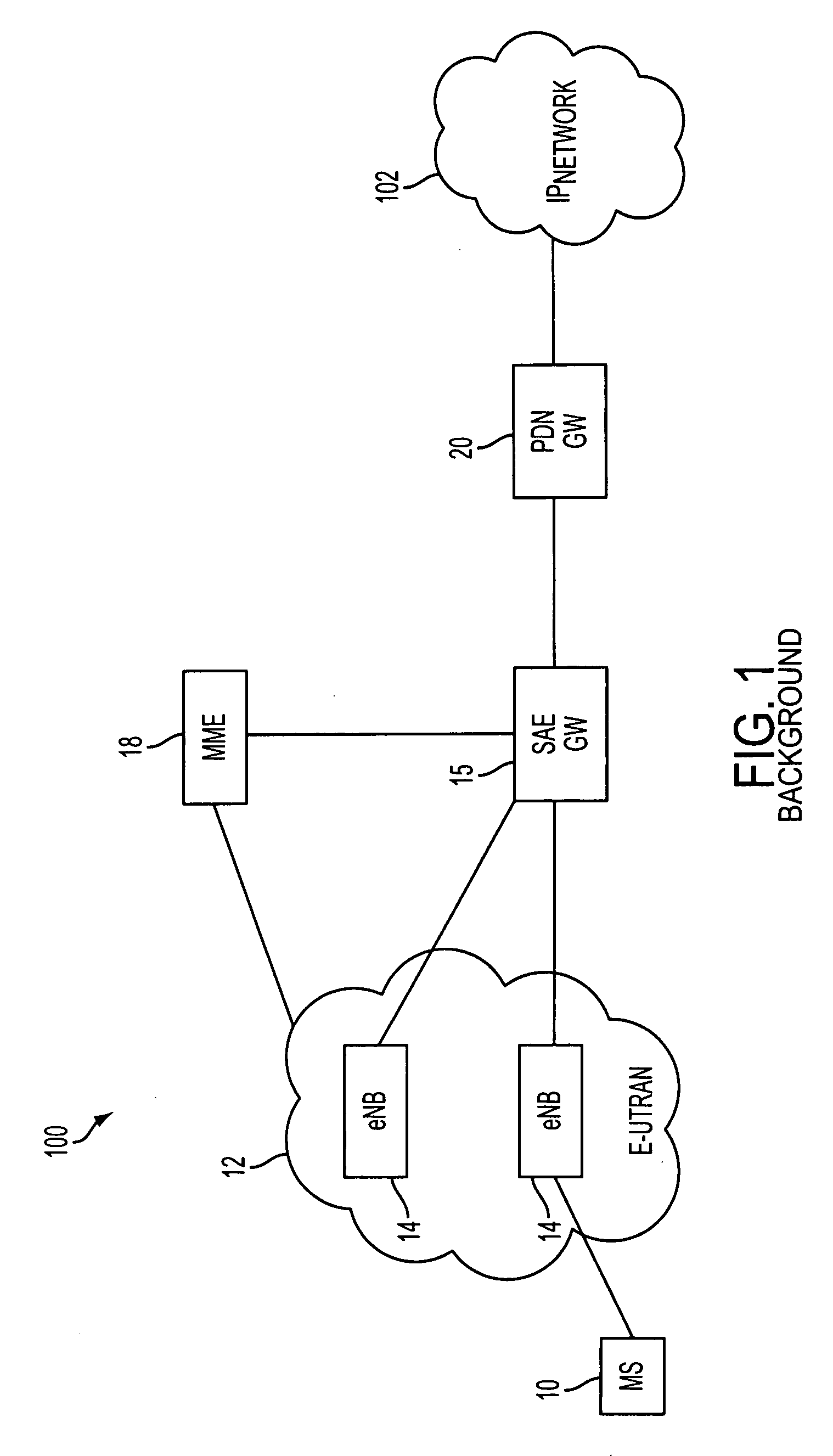
TECHNICAL FIELD[0001]This disclosure relates to wireless communication networks, and more particularly, to systems and methods for supporting handover performed when a user's mobile station (MS) moves from a wireless communication network that uses one radio access technology to a wireless communication network that uses another radio access technology.BACKGROUND[0002]A modern wireless communication network, such as a 3rd or 4th generation wireless network, combines a radio access network (RAN) with an Internet Protocol (IP) network. The RAN supports wireless connectivity over the airlink with a user's mobile station (MS), whereas the IP network provides the MS with access to IP services. For example, FIG. 1 illustrates a wireless communication network 100 based on the Evolved 3rd Generation Partnership Program (3GPP) Packet Switching Domain.[0003]The wireless network 100 involves a radio access technology that enables an MS 10 to access an IP network 102 over an Evolved Universal T...

Claims


Application Information

Patent Timeline
IPC IPC(8): H04Q7/20
CPCH04L45/00H04W36/0016H04W92/24H04W36/14H04W36/0033H04W36/1443
Inventor KOTECHA, LALIT RATILALYANG, JIN
Owner CELLO PARTNERSHIP DBA VERIZON WIRELESS
Learn More