Network device, communication method, program, and recording medium

a network device and communication method technology, applied in the field of network devices, communication methods, programs, and recording media, can solve problems such as interference in communication

Active Publication Date: 2018-02-27
ALLIED TELESIS
View PDF22 Cites 3 Cited by
  • Summary
  • Abstract
  • Description
  • Claims
  • Application Information

AI Technical Summary

Benefits of technology

[0022]It is therefore an object of the present invention to avoid the disability of the detection of the LDF due to the broadcast storm.

Problems solved by technology

When a loop is generated in this way, a communication is interfered.

Method used


Image

  • Network device, communication method, program, and recording medium
  • Network device, communication method, program, and recording medium
  • Network device, communication method, program, and recording medium

Examples


Embodiment Construction

[0045]A description will now be given of an embodiment of the present invention referring to drawings.

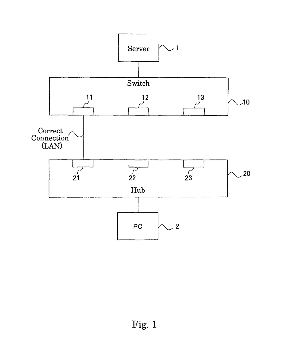
[0046]FIG. 1 is a diagram showing a network configuration if a switch 10 according to an embodiment of the present invention is correctly connected to a hub 20.

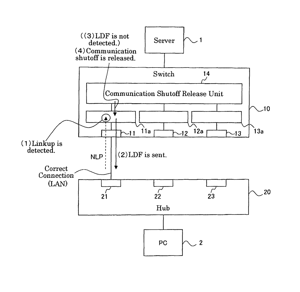
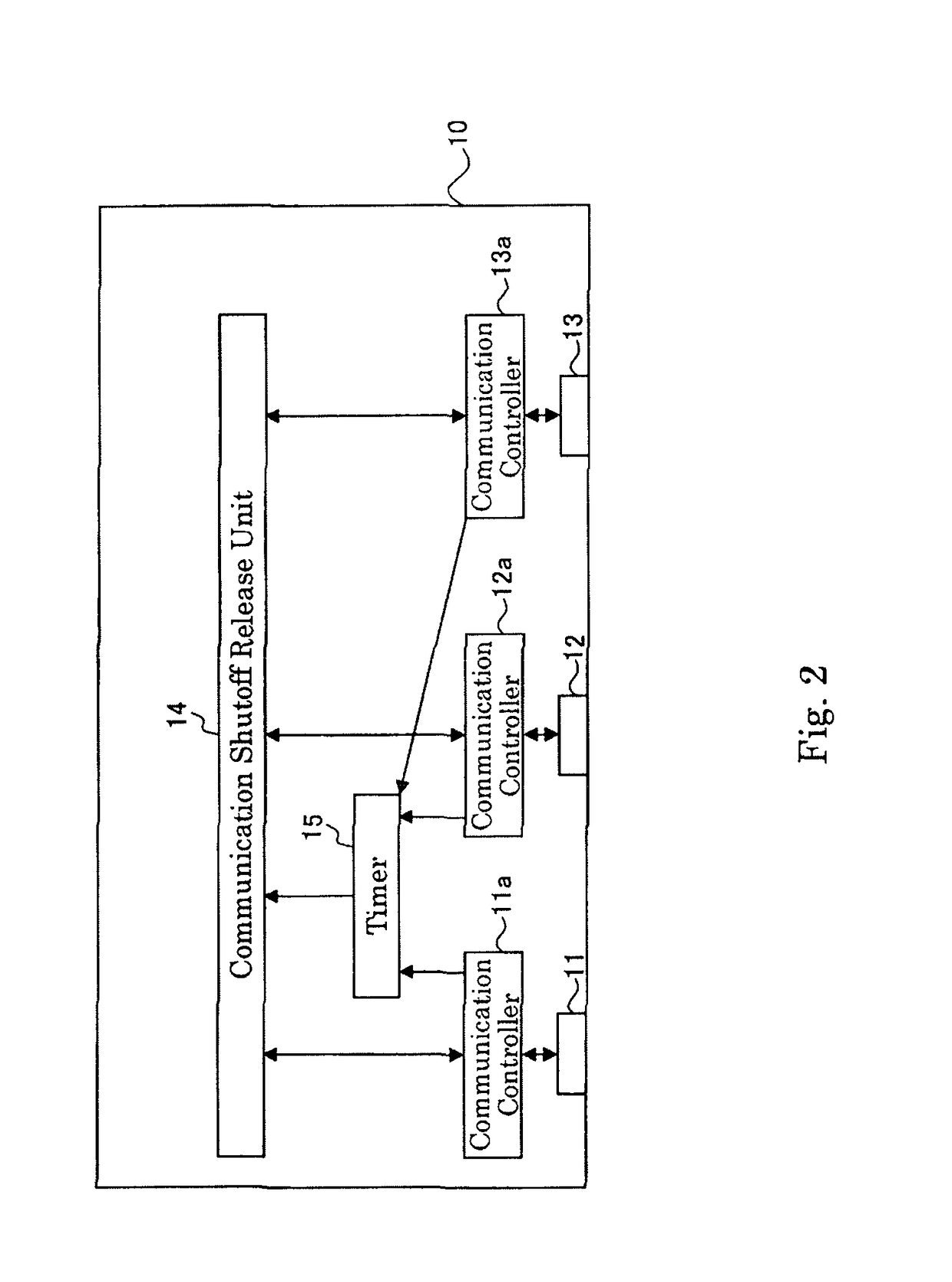
[0047]The switch (network device) 10 according to the embodiment of the present invention includes a plurality of ports 11, 12, and 13. The hub (another network device) 20 is connected to the switch 10. The hub 20 also includes a plurality of ports 21, 22, and 23. A server 1 is connected to the switch 10, and a PC (personal computer) 2 is connected to the hub 20.

[0048]The port 11 of the switch 10 and the port 21 of the hub 20 are connected with each other via a local area network (LAN). The port 11 of the switch 10 and the port 21 of the hub 20 are connected with each other via a well-known communication cable (such as 1000BASE-T cable), for example. This connection enables correct communication between the server 1 and the P...


PUM


Abstract

According to the present invention, a network device includes a plurality of ports which are connected to a LAN; a communication controller; and a communication shutoff release unit. The communication controller includes: a linkup detection unit, a loop detection frame sending out unit that sends out the loop detection frame from a linkup detected port, which is a port for which the linkup is detected, after a predetermined period from a time point when the linkup is detected by the linkup detection unit to the local area network, and a loop detection frame detection unit that detects the loop detection frame if the loop detection frame is received on the each port. The communication shutoff release unit releases the shutoff of the communication on the linkup detected port only if the loop detection frame is not detected by the loop detection frame detection unit.

Description

BACKGROUND OF THE INVENTION[0001]1. Field of the Invention[0002]The present invention relates to dissolution of a loop relating to a network device (such as a switch).[0003]2. Related Art[0004]When a network device is connected incorrectly, a loop may be generated.[0005]FIGS. 11(a) and 11(b) are diagrams showing an example of a network configuration in which a loop is generated according to prior art, and showing an example (FIG. 11(a)) of the network configuration before a loop is generated and an example (FIG. 11(b)) of the network configuration after the loop is generated.[0006]Referring to FIG. 11(a), a port 101 of the switch 100 and a port 201 of a hub 200 are correctly connected by a local area network (LAN). It should be noted that the switch 100 includes ports 102 and 103 in addition to the port 101, and the hub 200 includes ports 202 and 203 in addition to the port 201.[0007]However, referring to FIG. 11(b), the port 103 of the switch 100 and the port 203 of the hub 200 are...

Claims


Application Information

Patent Timeline
Patent Type & Authority Patents(United States)
IPC IPC(8): H04L12/26H04L12/705H04L45/18
CPCH04L43/0811H04L45/18H04L43/50
Inventor IKEGAMI, TOKUNORI
Owner ALLIED TELESIS
Why Eureka
Try Eureka