Modular holographic sighting system

a holographic and module technology, applied in the field of modules of holographic sighting systems, can solve the problems of obstructing the view of the rear and front sight, difficult to learn the iron sight method, and telescopic sights, while accurate, are not suited to situations where the target is located, so as to improve diffraction efficiency and image resolution, eliminate hysteresis during focusing, and reduce the effect of optical aberration

Active Publication Date: 2018-03-06
ZIEGER CORY DR
View PDF76 Cites 13 Cited by
  • Summary
  • Abstract
  • Description
  • Claims
  • Application Information

AI Technical Summary

Benefits of technology

[0011]The holographic sighting system has entirely fixed on-axis optical and holographic elements thereby providing the least amount of optical aberration over a wide temperature range. The system further includes fine grain holographic silver halide plates to improve diffraction efficiency and image resolution.
[0012]The lower housing assembly of the holographic sighting system includes a modular base system that provides both vertical and horizontal aiming for the sighting system and eliminates the need for relative motion between optical elements. The modular base system is configured for attaching various sizes of the sighting system to a firearm while providing accurate windage and elevation adjustments.
[0013]The holographic sighting system also includes a laser diode carrier for mounting the laser diode light, the laser diode carrier being attached to a flexible circuit that allows the laser diode to be adjusted via a set of alignment controllers connected between the lower housing assembly and to the laser diode carrier. The set of alignment controllers further include tensioning springs that provide an outward bias to the laser diode carrier that opposes the tightening action of the set of alignment controllers and eliminate hysteresis during focusing

Problems solved by technology

The iron sight method, while reliable, can be difficult to learn and has multiple drawbacks including the rear and front sight obstructing the view of the target and complications arising from sub-optimal lighting conditions.
Telescopic sights, while accurate, are not suited for situations where the target is moving, close quarter conditions, or if the shooter is mobile.
Laser designator sights, where a laser beam illuminates the target can be difficult to use in certain lighting conditions and are unacceptable for military or self-defense applications where the shooters location must not be revealed.
Red dot sighting systems—Reflex-, such as those provided by AimPoint® solve many of the above difficulties, but are only able to project a single dot reticule pattern due to off-axis aberrations.
However, currently available HWS systems suffer from drawbacks related to their design and technique of manufacturing.
Current HWS products utilize an internal mechanism to adjust reticule position, which alters the achromatic geometry of the system when aiming adjustments are made, thereby compromising the ability of the wavelength dispersion compensation elements to perform as intended.
In addition to compromised wavelength dispersion matching, current HWS products also suffer from reticule pattern distortion as a result of the mechanical stresses created from the internal adjustment mechanism.
The wavelength stabilizing holographic optical element is bonded to a plastic flexible element, creating a system that is susceptible to wave front aberrations brought about by changes in temperature to the hologram and mounting substrate.
Any variability induced by workmanship and manufacturing methods affects the integrity and effectiveness of the seal over time.
The flat rubber and o-ring sealing system is often compromised by the stresses caused from changing ambient temperature and pressure conditions, resulting in continued cycling of the housing cavity pressure, which tends to make the flat gasket method of sealing failure prone.
As a consequence, systems sealed in this manner tend to leak, allowing moisture to permeate the holographic elements resulting in fading of the reticule image.
However, inconsistencies in the production of this off center section introduce aberrations and increases production costs.
Finally, current designs for HWS systems lack modularity, and minor changes to mounting systems, optical path, reticule patterns, and battery type require a complete re-design and re-tooling in order to implement the changes.

Method used


Image

  • Modular holographic sighting system
  • Modular holographic sighting system
  • Modular holographic sighting system

Examples


Embodiment Construction

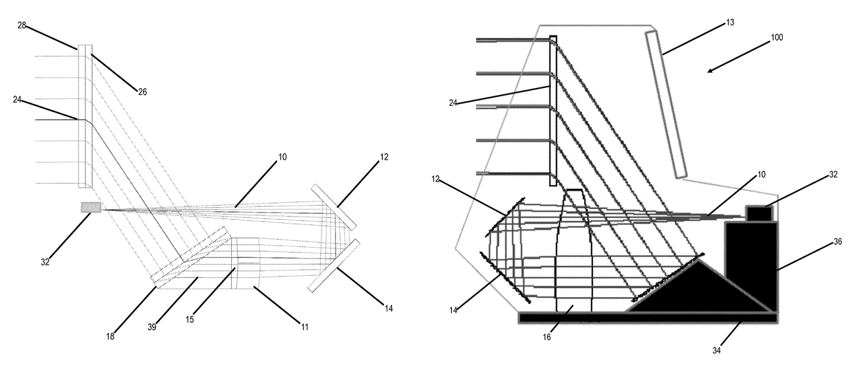
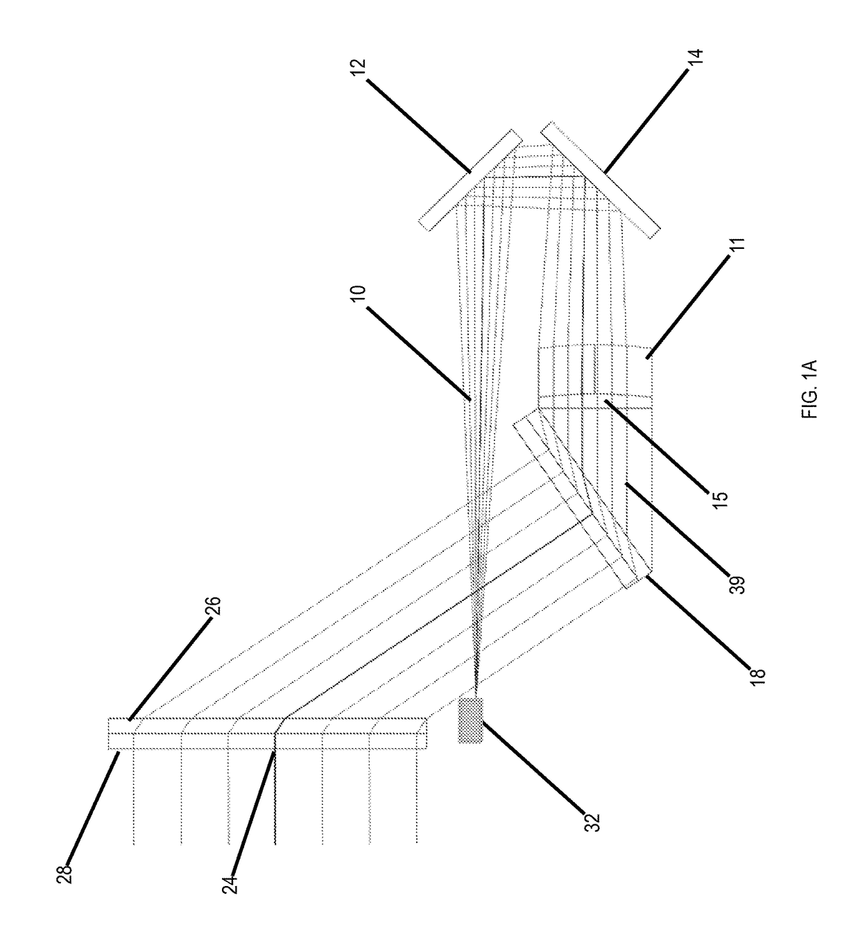
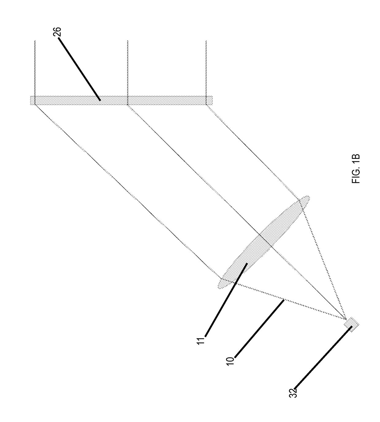
[0020]The present invention has utility as a lightweight holographic sighting system specifically designed to minimize optical aberrations common with earlier holographic sighting systems with a modular construction that is more economic and conducive to high volume production, in terms of complexity of required fixturing and availability of materials, than earlier systems. Embodiments of the invention provide a holographic sighting system that is lighter and more compact (shorter in length), while providing a larger field of view than existing systems that can be used on small hand guns, standard size firearms, bows, telescopes, and other devices without adding significant weight or space constraints. Embodiments of the inventive sighting system utilize an upper housing assembly containing a high efficiency holographic optical element, an anti-reflective glass viewing window, and a red diode laser light source driven by a high efficiency microcontroller circuit designed for increas...


PUM


Abstract

A lightweight holographic sighting system is provided that is designed to minimize optical aberrations common with earlier holographic sighting systems. The system has a modular construction that is more economic and conducive to high volume production, in terms of complexity of required fixturing and availability of materials, than earlier systems. The system is lighter and more compact, while providing a larger field of view than existing systems, and can be used on small hand guns, standard size firearms, bows, telescopes, and other devices without adding significant weight or space constraints. The system utilizes an upper housing assembly containing a high efficiency holographic optical element, an anti-reflective glass viewing window, and a red diode laser light source driven by a high efficiency microcontroller circuit designed for increased battery life, and a lower housing assembly containing two dielectric folding mirrors, an on-axis collimating lens, and a high efficiency achromatizing holographic optical element.

Description

RELATED APPLICATIONS[0001]This application claims priority benefit of U.S. Provisional Application Ser. No. 61 / 844,254 filed Jul. 9, 2013; the contents of which are hereby incorporated by reference.FIELD OF THE INVENTION[0002]The present invention in general relates to holographic sighting devices and in particular, to a holographic sighting system that is lightweight, waterproof, and modular and can be used on small firearms, bows, telescopes, and other applications where aiming is necessary.BACKGROUND OF THE INVENTION[0003]Multiple sighting methods for aiming firearms have been utilized for both commercial and military applications. The most basic, the iron sight, requires the shooter to align the rear sight, front sight, and the target while switching the eye's point of focus between the rear and front sight pattern and the target. The iron sight method, while reliable, can be difficult to learn and has multiple drawbacks including the rear and front sight obstructing the view of...

Claims


Application Information

Patent Timeline
Patent Type & Authority Patents(United States)
IPC IPC(8): G02B5/32F41G1/14G02B23/14F41G1/34G02B27/42G02B27/20G02B27/00G02B17/02G02B19/00
CPCG02B23/14F41G1/14F41G1/345G02B5/32G02B27/42G02B19/0052G02B27/0025G02B27/20G02B17/023
Inventor ARMBRUSTER, ROBIN C.BRINCAT, JOSEPH ANTHONYFISH, ROBERT H.KARATSINIDES, PAULJUNKINS, KENNETH M.
Owner ZIEGER CORY DR
Why Eureka
Try Eureka