
Wrap dispensing apparatus

a technology for dispensing equipment and wrapping paper, which is applied in the direction of conveyor wrapping, transportation and packaging, packaging, etc., can solve the problems of operator fatigue and discomfort, acute discomfort, fatigue, stress-related injuries, etc., and achieves convenient and efficient manufacturing and marketing, easy assembly, and durable and reliable construction

Inactive Publication Date: 2008-10-21
MOSER ROBERT E
View PDF17 Cites 7 Cited by
  • Summary
  • Abstract
  • Description
  • Claims
  • Application Information

AI Technical Summary

Benefits of technology

"The present invention is an apparatus for wrapping material around pallets or articles to be banded together. It allows for easy and efficient wrapping of loads on pallets without physical exertion. The apparatus has a base, hub assembly, and threaded spindle with a roll of material mounted thereon. It has a steering arm for easy movement around the load and a braking system to stop the spindle. The apparatus can be easily manufactured, marketed, and assembled. It also allows for easy adjustment of tension on the film and can be used by operator personnel who can simply walk around the pallet and push or guide the roll of film around the load. The apparatus can be used to apply wrapping film to the entire vertical extent of the load without support or bending down."

Problems solved by technology

In accordance with either one of the afore-noted modes, methods, or manners in which stretch film is applied manually to the palletized products or loads, several operational drawbacks or disadvantages common to both methods or modes were apparent.
Firstly, for example, the film roll, or the film roll and film roll dispensing or holding device, must be supported by the operator personnel, and yet the film roll and the film roll dispensing or holding device are quite heavy and cumbersome.
Such requirements upon the operator personnel have been noted to cause acute discomfort, fatigue, and stress-related injuries.
In addition, the operators experience fatigue and discomfort even when the operators are wrapping the upper regions of the palletized loads or products due to the continuous need for supporting the entire weight of the film roll, or the film roll and film roll dispensing or holding device.

Method used


Image

  • Wrap dispensing apparatus
  • Wrap dispensing apparatus
  • Wrap dispensing apparatus

Examples


Embodiment Construction

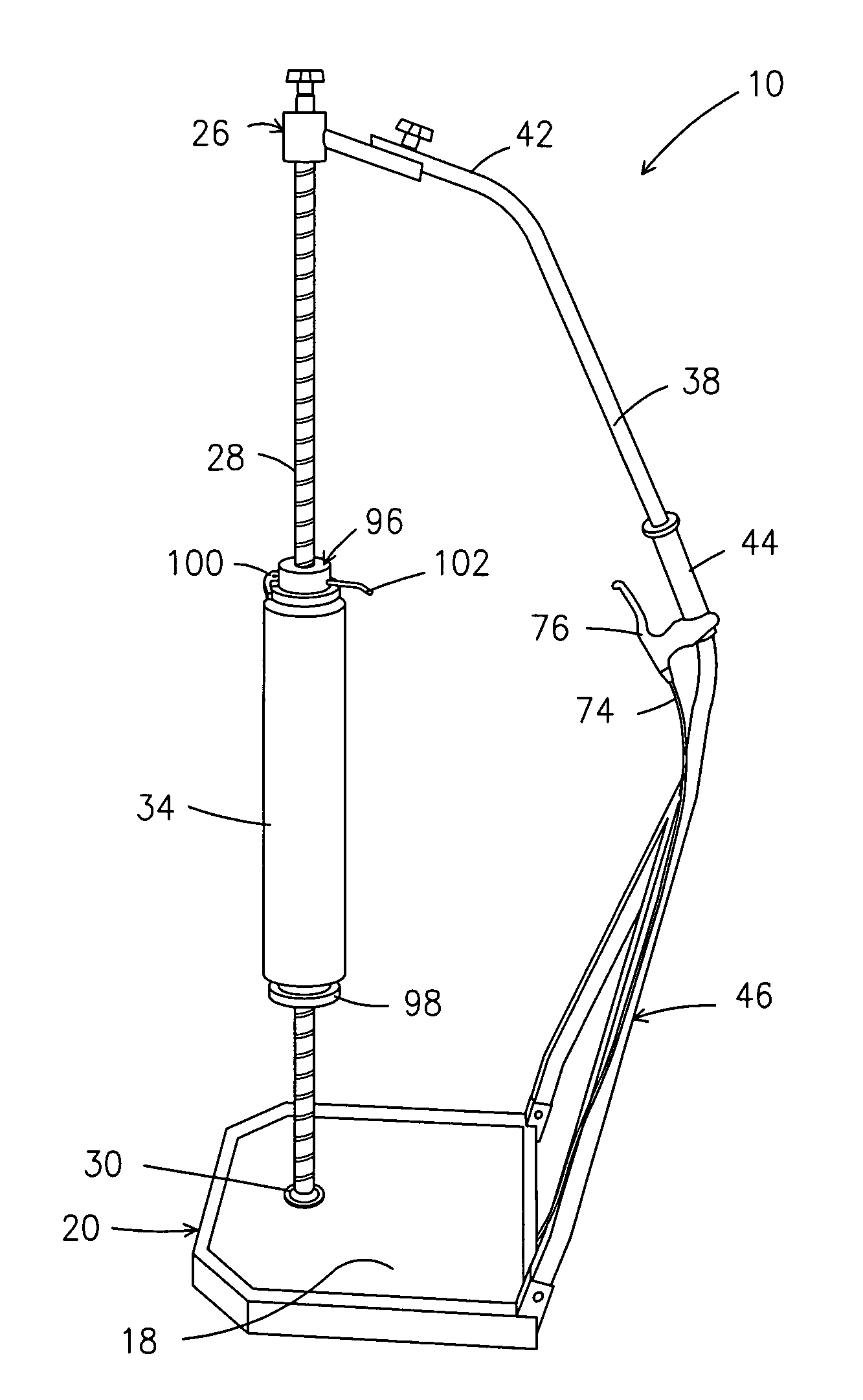
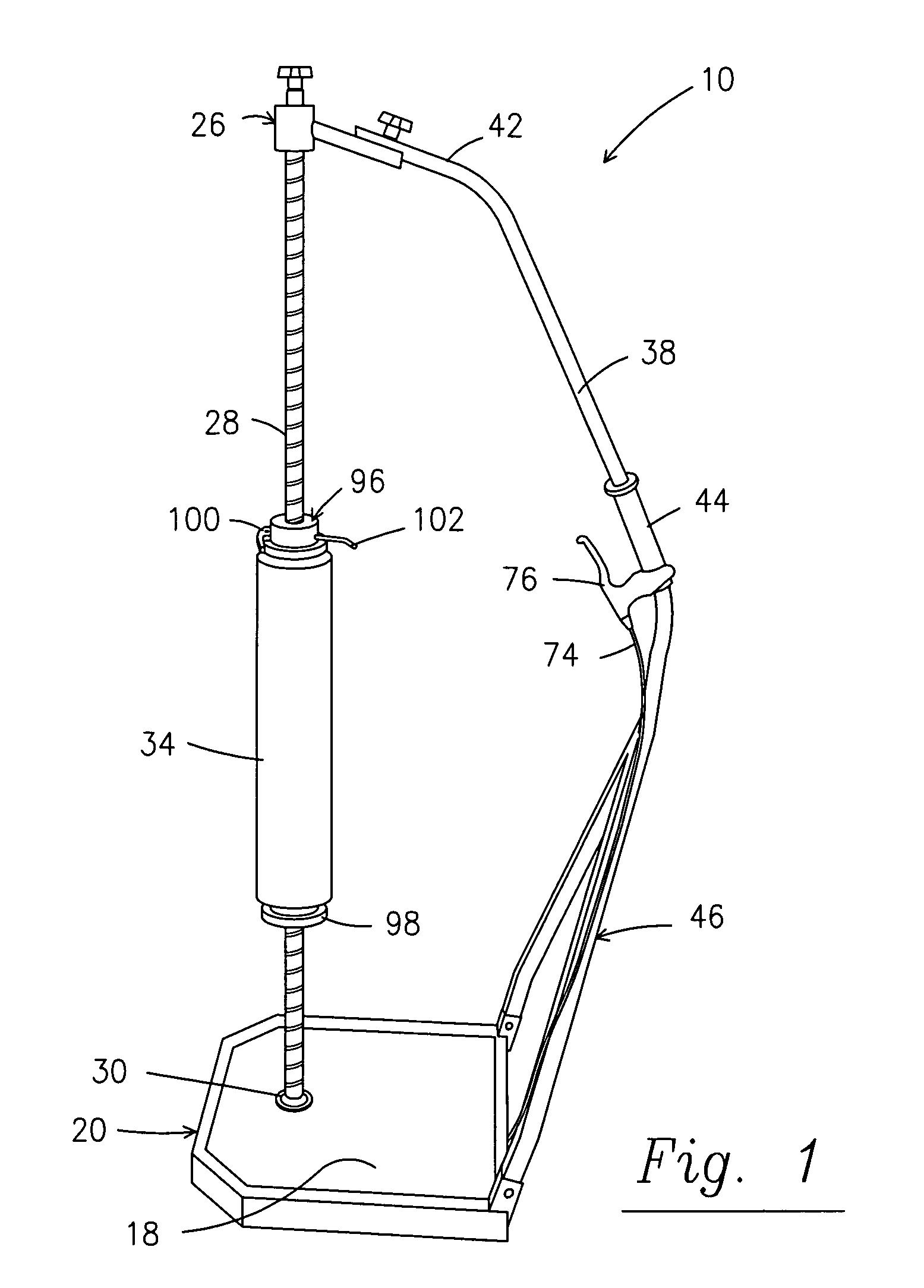
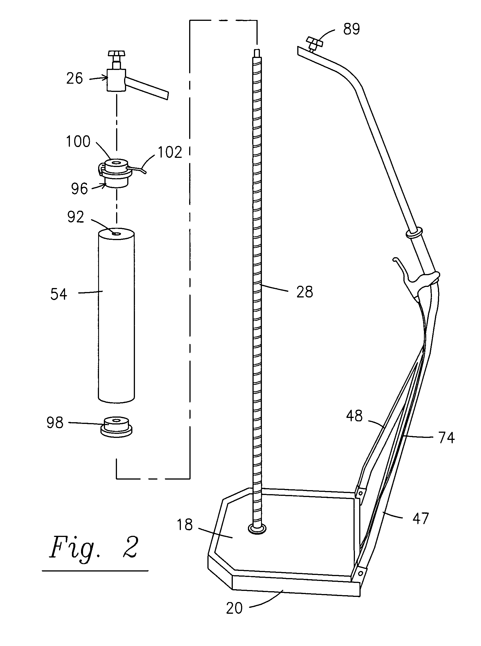
[0037]With reference now to the drawings, and in particular to FIGS. 1-7 thereof, a wrap dispensing apparatus 10 embodying the principles and concepts of the present invention and generally designated by the reference numeral 10 will be described.

[0038]The present invention, the new and improved wrap dispensing apparatus, is comprised of a plurality of components. Such components in their broadest context include a base, a hub assembly, a steering arm, a threaded spindle and a brake assembly. Such components are individually configured and correlated with respect to each other so as to attain the desired objective.

[0039]More specifically, the present invention is a wrap dispensing apparatus for wrapping an article with wrapping material. The apparatus of FIG. 1 includes a base 20 that is made of a rigid material. A hub assembly 24 is coupled to a threaded spindle 28 that has a lower end positioned within the upper bearing 30 mounted onto the base. The threaded spindle can be rotated...


PUM

PropertyMeasurementUnit
tensionaaaaaaaaaa
rotational movementaaaaaaaaaa
rotationaaaaaaaaaa

Abstract

A wrap dispensing apparatus for wrapping an article with wrapping material includes a base; a hub assembly; a threaded spindle mounted to the base and the hub assembly, and a brake assembly to control the movement of the threaded spindle. The threaded spindle supports a roll of material between the base and the hub assembly. Further included is a steering arm that is attached to the base and the hub assembly and spaced from the threaded spindle. The base has wheels for omni-directional movement along a horizontal surface.

Description

BACKGROUND OF THE INVENTION[0001]1. Field of the Invention[0002]The present invention relates to a wrap dispensing apparatus and more particularly pertains to mobile wrapping apparatus for wrapping material about a load or items to be banded.[0003]2. Description of the Related Art[0004]The use of portable film wrapping systems is known in the prior art. More specifically, film wrapping systems heretofore devised and utilized for the purpose of wrapping film about a load carried on a pallet are known to consist basically of familiar, expected and obvious structural configurations, notwithstanding the myriad of designs encompassed by the crowded prior art which have been developed for the fulfillment of countless objectives and requirements.[0005]In the stretch wrapping of loads carried on pallets, a sheet of material is spirally wrapped about the load on the pallet. By way of example, the prior art includes U.S. Pat. No. 6,742,322, which has a portable plastic film wrapping system th...

Claims


Application Information

Patent Timeline
Patent Type & Authority Patents(United States)
IPC IPC(8): B65B11/28
CPCB65B11/025B65B67/08
Inventor MOSER, ROBERT E.MORRISON, GEORGE E.
Owner MOSER ROBERT E
Learn More