Craniofacial surgery implant systems and methods

a technology of implant systems and craniofacial bones, applied in the field of surgical implants, can solve problems such as inability to meet patients, inconvenient operation, and inefficient current techniques, and achieve the effects of avoiding complications, avoiding complications, and avoiding complications

Active Publication Date: 2018-03-13
YAREMCHUK MICHAEL J M D
View PDF45 Cites 9 Cited by
  • Summary
  • Abstract
  • Description
  • Claims
  • Application Information

AI Technical Summary

Benefits of technology

[0008]In one aspect, the present invention relates to craniofacial implants including a base implant and an optional onlay component that is contoured to the surface of the base implant allowing the overall projection of the implant to be adjustable.

Problems solved by technology

Problems can exist, however, due to the relatively large size of some of the implants (e.g., requiring more extensive surgical access to the area to be augmented) and / or the amount of customization and associated time required, due to the limited selection of implants in each family.
Implants of different sizes must be custom carved and, in extreme cases, stacked and joined together by sutures if standard implants are not ideal for specific clinical situations.
Current techniques can be inefficient and imprecise, and intraoperative constructs might be unstable in shape, leading to unpredictable outcomes.
Further, the outcome can be less than ideal when the surgeon commits to opening an implant that, after placement, is less than ideal in projection.
The precise positioning of facial implants by the surgeon during the implant procedure is often difficult and time consuming, due to limited exposure of the areas to be augmented.
Accurate implant placement is especially difficult when attempting to place a pair of implants symmetrically.
For example, symmetric placement of facial implants can be problematic due to the complex three-dimension surface of the facial skeleton and limited surgical exposure.
Available conventional clamps (e.g., tissue forceps, bone reduction forceps, towel clips, etc.) do not provide stable purchase of the implant and bone, due to their purchase end design, the dimensions of the purchasing end, and the configuration and orientation of the purchasing end.
Inadvertent movement of the implant while it is being secured can result in implant malposition and, if recognized intraoperatively, the need to remove and reposition the implant.

Method used


Image

  • Craniofacial surgery implant systems and methods
  • Craniofacial surgery implant systems and methods
  • Craniofacial surgery implant systems and methods

Examples


Embodiment Construction

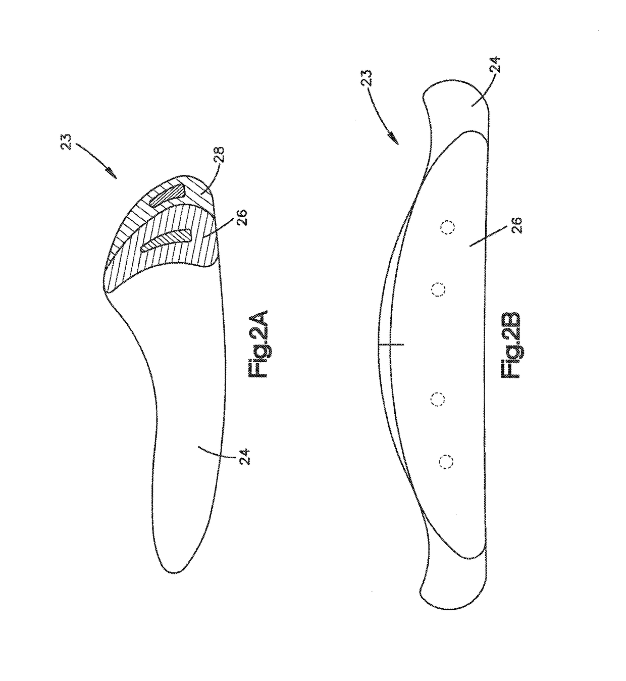
[0057]According to various embodiments of this invention, implants can be made in multiple mating pieces to reduce the inventory of implants required, while providing a high level of customization with limited sculpting or custom shimming by the surgeon during the implant procedure. While porous polyethylene material may be used, the invention is not limited in this regard and any suitable biocompatible material may be employed (e.g., rigid or flexible, porous or nonporous, polymer or nonpolymer, etc.). The implants of the present invention may be provided in kit form with or without fasteners and / or conventional or specialized surgical instruments described herein.

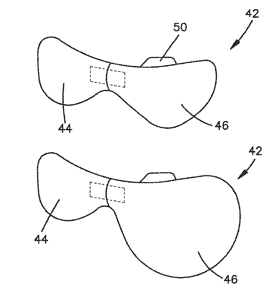
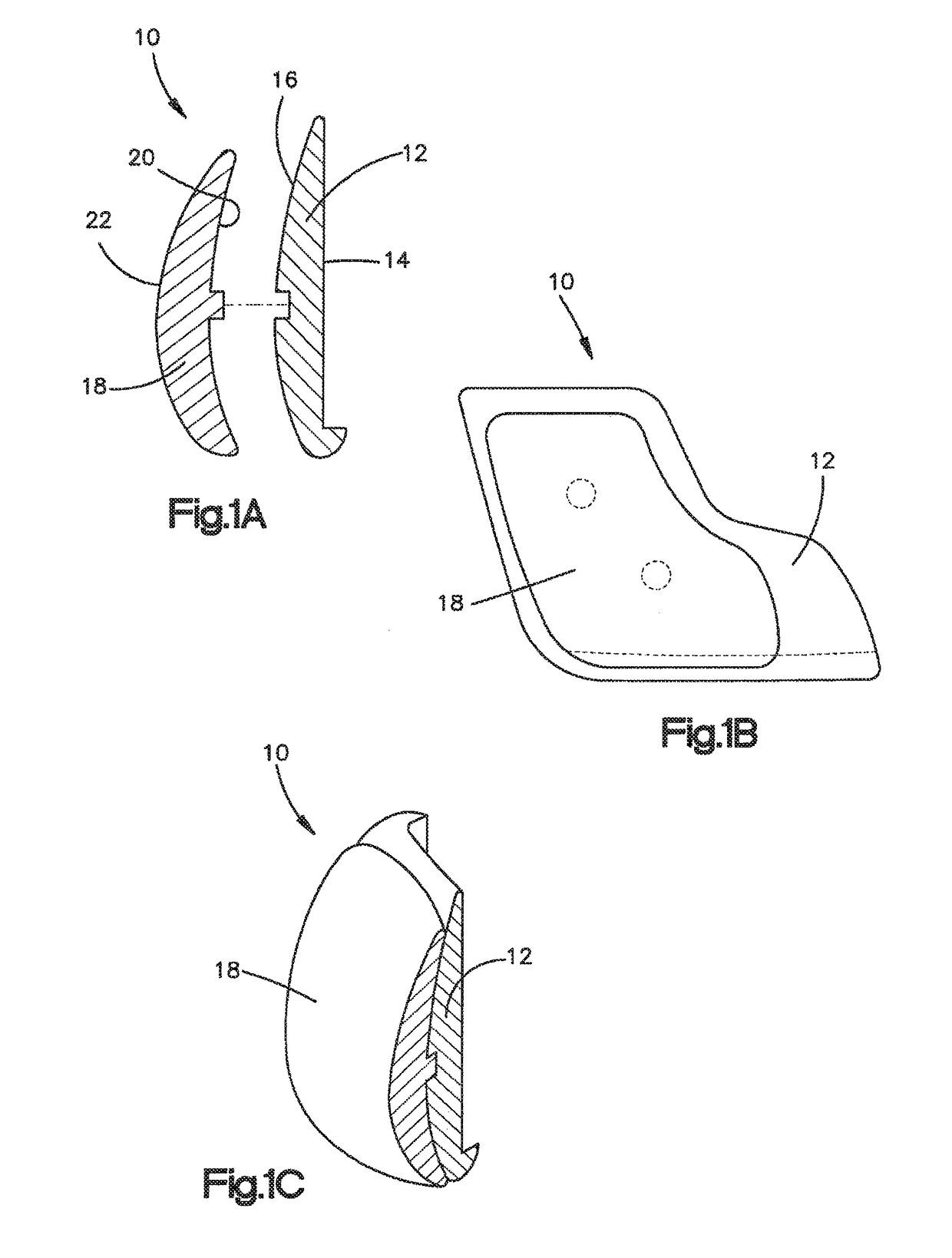
[0058]A first embodiment, an example of which is shown in FIG. 1, provides implants with adjustable projection. A two or more piece layered configuration provides controlled variability in the amount of augmentation provided by a single implant. In general, this embodiment relates to a craniofacial implant 10 including a ...


PUM


Abstract

Various embodiments of craniofacial implants, surgical instruments, and techniques are described to provide improved surgical results.

Description

CROSS-REFERENCE TO RELATED APPLICATIONS[0001]This application claims priority to and incorporates by reference the entire disclosure of each of the following three provisional U.S. patent applications: U.S. Ser. No. 61 / 018,943 filed Jan. 4, 2008, titled “Multi-Component Craniofacial Surgery Implant Systems and Methods”; U.S. Ser. No. 61 / 018,948 filed Jan. 4, 2008, titled “Craniofacial Implant Registration Features and Methods”; and U.S. Ser. No. 61 / 018,952 filed Jan. 4, 2008, titled “Craniofacial Implant Surgical Instruments and Methods.”FIELD OF THE INVENTION[0002]The invention relates to surgical implants and more specifically to craniofacial implant systems and associated surgical methods employing multiple mating components and registration features on the implants. The invention further relates to surgical instruments and more specifically to craniofacial implant surgical instruments and associated surgical methods.BACKGROUND OF THE INVENTION[0003]Craniofacial surgery is genera...

Claims


Application Information

Patent Timeline
Patent Type & Authority Patents(United States)
IPC IPC(8): A61F2/02
CPCA61F2/02A61F2/0059A61F2/2875A61F2/30942A61F2/4601A61F2002/30522A61F2002/30578A61F2002/30616A61F2002/30736A61F2002/4622A61F2002/30331
Inventor YAREMCHUK, MICHAEL J.
Owner YAREMCHUK MICHAEL J M D
Why Eureka
Try Eureka