Ladder-supporting gutter clamping system

a technology of gutter clamping and support rod, which is applied in the direction of clamping, construction, manufacturing tools, etc., can solve the problems of not being able to meet the needs of construction workers, too large and clunky, and too expensive, and achieve the effect of restricting upward movemen

Inactive Publication Date: 2018-03-13
LADDER MATES USA
View PDF31 Cites 6 Cited by
  • Summary
  • Abstract
  • Description
  • Claims
  • Application Information

AI Technical Summary

Benefits of technology

[0004]It is among the purposes of this invention to provide a gutter clamp that is simple, effective, and easy to use, being as close to “fool”-proof as possible, given the inordinate amount of people copping to the description. A gutter clamping system for restraining a two-legged extension ladder against movement when leaned against a gutter, the gutter clamping system comprising at least one gutter clamp, each gutter clamp including a) a clamp body having a first gutter-engaging surface for being positioned on a first side of a rim of a gutter; b) a latch having a second gutter-engaging surface for being positioned on a second opposite side of the rim of a gutter; c) a latch pin pivotably mounting the latch to the clamping body, the latch pin permitting the latch to pivot between a first unengaged position and a second position engaging the gutter clamping the rim of the gutter between the first gutter-engaging surface and the second gutter-engaging surface; d) spring means engaged between the clamp body and the latch biasing the latch to the second position; e) at least one ear protruding from a first side of the clamp body for engaging a ladder leg; whereby the gutter clamp system secures a ladder against movement along a gutter by clamping at least one of said clamps to a rim of the gutter adjacent and engaging a first side of one of the two legs of the extension ladder. Preferably, the system employs a pair of such clamps and the second of the pair of clamps is secured to a rim of the gutter adjacent and engaging an opposite side of the other of the two legs of the extension ladder. This may be the outsides of the two legs or the insides of the two legs; either will suffice to prevent the ladder from sliding along or pulling away from the gutter.
[0006]As additional protection against slippage of the clamp, a lock screw threaded through a portion of said clamp body is provided, the lock screw being adapted to engage an upper portion of the latch whereby when the lock screw engages the upper portion of the latch, the latch will not pivot to the first disengaged position. A stop is formed on a forward portion of a threaded portion of the lock screw preventing the lock screw from being removed from the clamp body. Preferably, each latch includes a finger adapted to extend beneath a lip on the rim portion of the gutter to restrict upward movement of the gutter clamp relative to the rim portion of the gutter.

Problems solved by technology

However, none of these products have proven satisfactory.
Some are too large and clunky; some too expensive; others simply do not perform as advertised.

Method used


Image

  • Ladder-supporting gutter clamping system
  • Ladder-supporting gutter clamping system
  • Ladder-supporting gutter clamping system

Examples


first embodiment

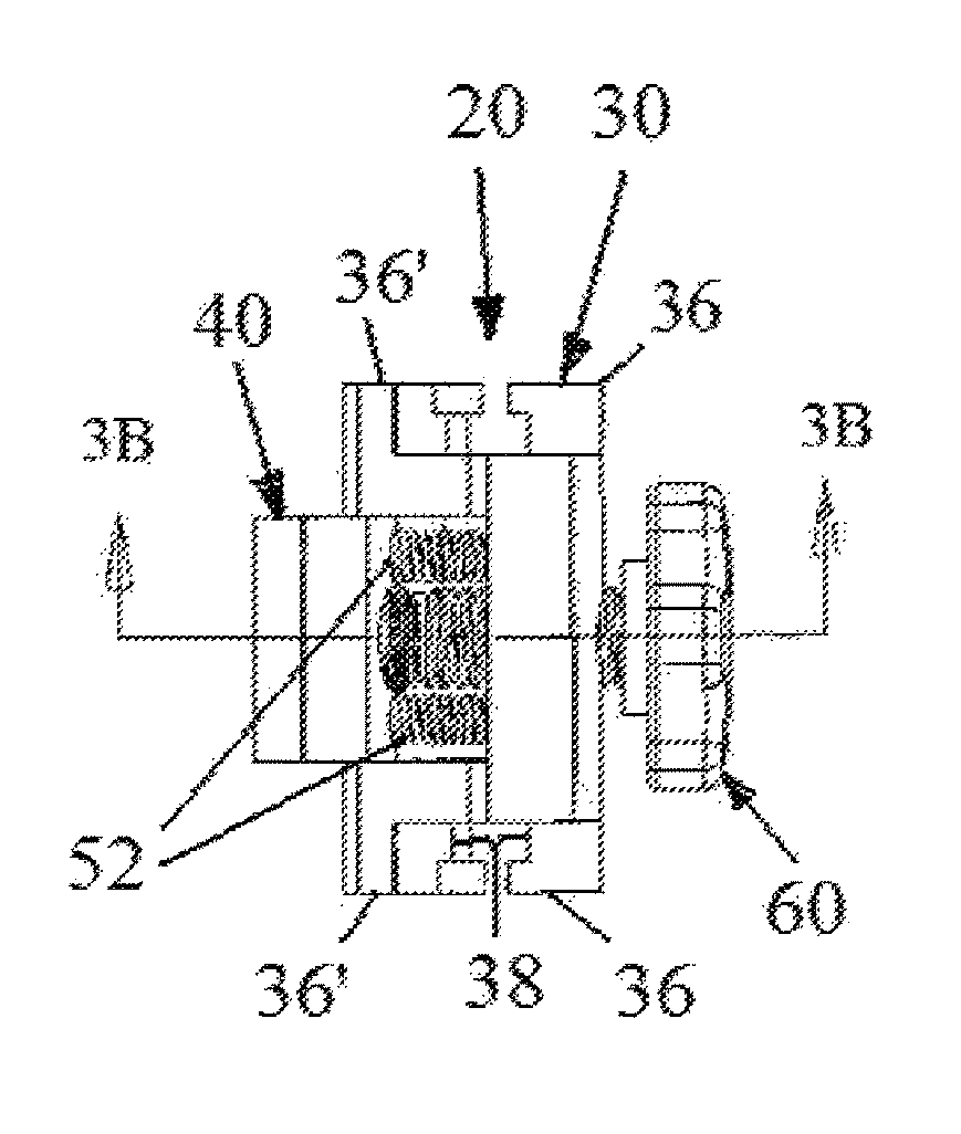
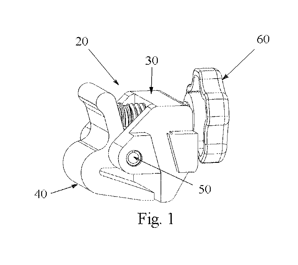
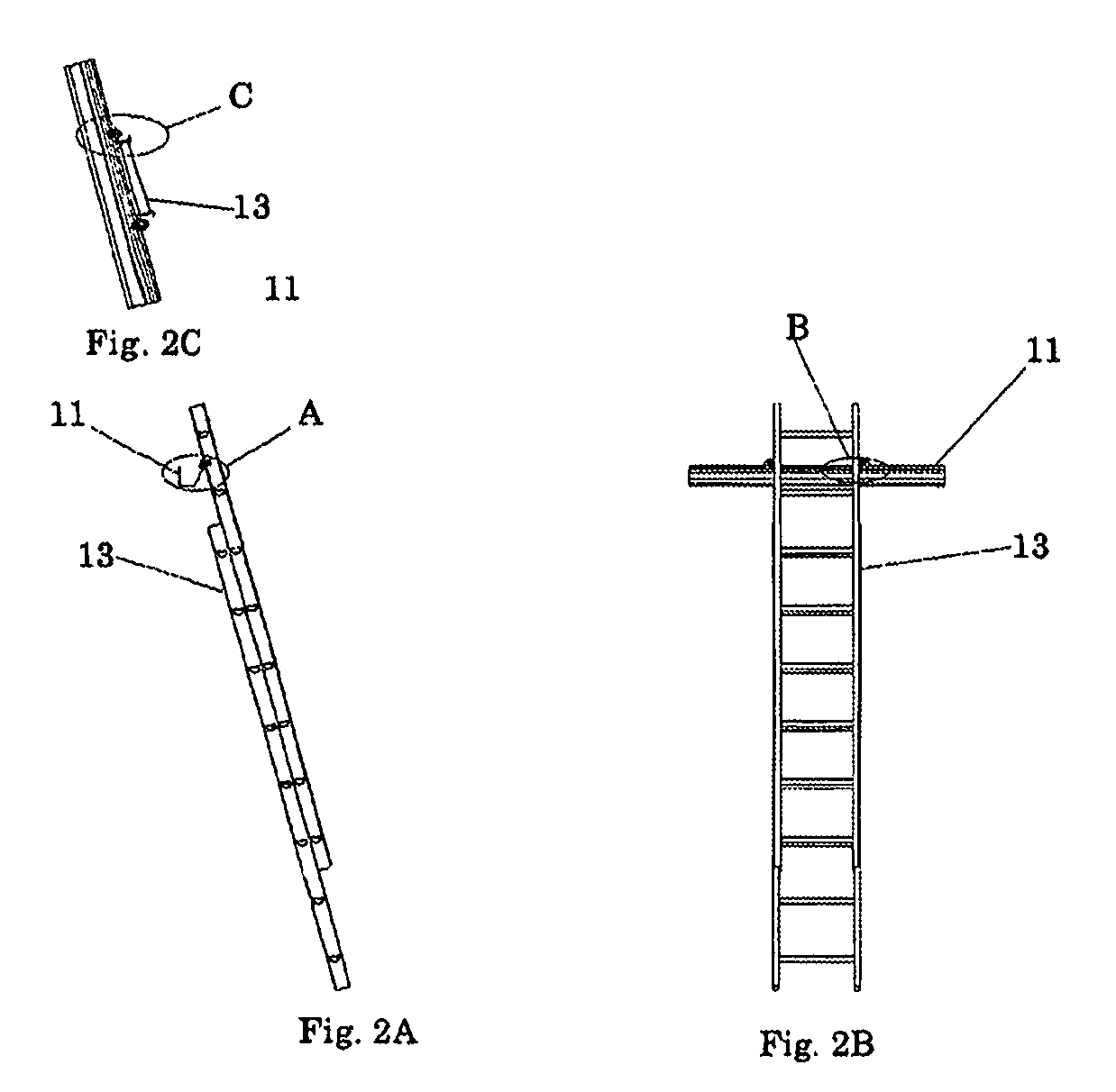
[0022]the gutter clamp used in the gutter clamp system of the present invention is depicted in FIGS. 1, 3-6 generally at 20. As best seen in FIGS. 1, 3A-3D, gutter clamp 20 comprises a clamp body 30 and a latch 40 pivotally attached to clamp body 30 by means of latch pin 50. When given its full range of motion, latch 40 can move between a first open position (FIG. 3D) and a second closed position (FIG. 3B) in which a first surface 32 on clamp body and a second surface 42 on latch 40 cooperate to grip opposite faces of gutter 11 (FIG. 5). Spring means comprises at least one spring, and more preferably a plurality of springs 52 engage between clamp body 22 and back surface 44 of latch 40 to bias latch 40 to its second closed position. The ends of springs 52 are seated in recesses (not shown) in each element to prevent slipping of the springs from their desired points of engagement. Depending on the spring rates of springs 52, the grip they afford on gutter 11 is sufficient to inhibit ...

second embodiment

[0024]the gutter clamp of the present invention is seen in FIGS. 5-8 generally at 20″. In this embodiment, the second ears 36′ are removed and ears 36″ provided with a radius which accommodates any angle at which ladder 13 is leaned enabling the slot 38″ to engage channel 15 under all circumstances. FIG. 8 depicts a first clamp 20a″ affixed to gutter 11 and a second clamp 20b″ attached to the leg 17 of ladder 13. Clamp 20″ can be attached to the ladder leg 17 prior to its being leaned against gutter 11 affording the climber hands-free gutter access.


PUM


Abstract

A clamping system for supporting an extension ladder on a gutter utilizes at least one and, more preferably, a pair of identical, clamp(s) to capture the ladder preventing movement laterally or horizontally away from the gutter. The clamp includes a clamp body with a latch pivotably mounted thereto which is spring biased to the gutter-clamping position. A lock screw may be utilized to prevent the latch from releasing the gutter preventing the ladder from moving. A pair of ears extends from each side of the clamp body and have slots which engage the channels on a forward face of the ladder leg.

Description

BACKGROUND AND SUMMARY OF THE INVENTION[0001]The present invention is directed to the field of safety equipment. More particularly, the present invention comprises a clamping system including at least one, and preferably, a pair of clamp(s) which securely attach to a gutter adjacent each of the legs of an extension ladder preventing the ladder from sliding along or pulling away from the gutter and depositing its climber on the ground.[0002]It would seem that as Autumn comes round on the calendar, the season gives another reason for associating the term “Fall” with it: numerous reports of ladder users' injuries, both professionals and DIYers, adorn the newspapers resulting from ladders slip-sliding along gutters resulting in each of these users taking a fall.[0003]Quite a few attempts to provide a solution to this problem have been made to-date. However, none of these products have proven satisfactory. Some are too large and clunky; some too expensive; others simply do not perform as...

Claims


Application Information

Patent Timeline
Patent Type & Authority Patents(United States)
IPC IPC(8): E06C7/48B25B5/10
CPCB25B5/103E06C7/486
Inventor DURFEE, III, DAVID DAVY L.
Owner LADDER MATES USA
Why Eureka
Try Eureka