Part polishing device

A technology of parts and grinding discs, which is applied in the field of mechanical processing equipment, can solve the problems of high work intensity, low efficiency, and low work efficiency, and achieve the effect of improving processing efficiency and high efficiency

Inactive Publication Date: 2018-07-27
宁波鑫神泽汽车零部件有限公司
View PDF4 Cites 6 Cited by
  • Summary
  • Abstract
  • Description
  • Claims
  • Application Information

AI Technical Summary

Problems solved by technology

[0003] In the prior art, the manual method is usually used to remove the burr on the surface of the part by using a file or a hammer. This method has low work efficiency and high work intensity
For the deburring of pipe parts, it is usually necessary to polish the inner and outer surfaces. When grinding the outer surface, fix the pipe by fixing the inner wall of the pipe, and then use a grinding tool to polish the outer surface of the pipe; when grinding the inner surface, fix the pipe by The outer wall of the pipe is fixed, and then the inner wall of the pipe is polished with a grinding tool. In this process, the parts need to be fixed and polished twice, which is very inefficient.

Method used


Image

  • Part polishing device
  • Part polishing device
  • Part polishing device

Examples


Embodiment Construction

[0022] The present invention will be described in further detail below by means of specific embodiments:

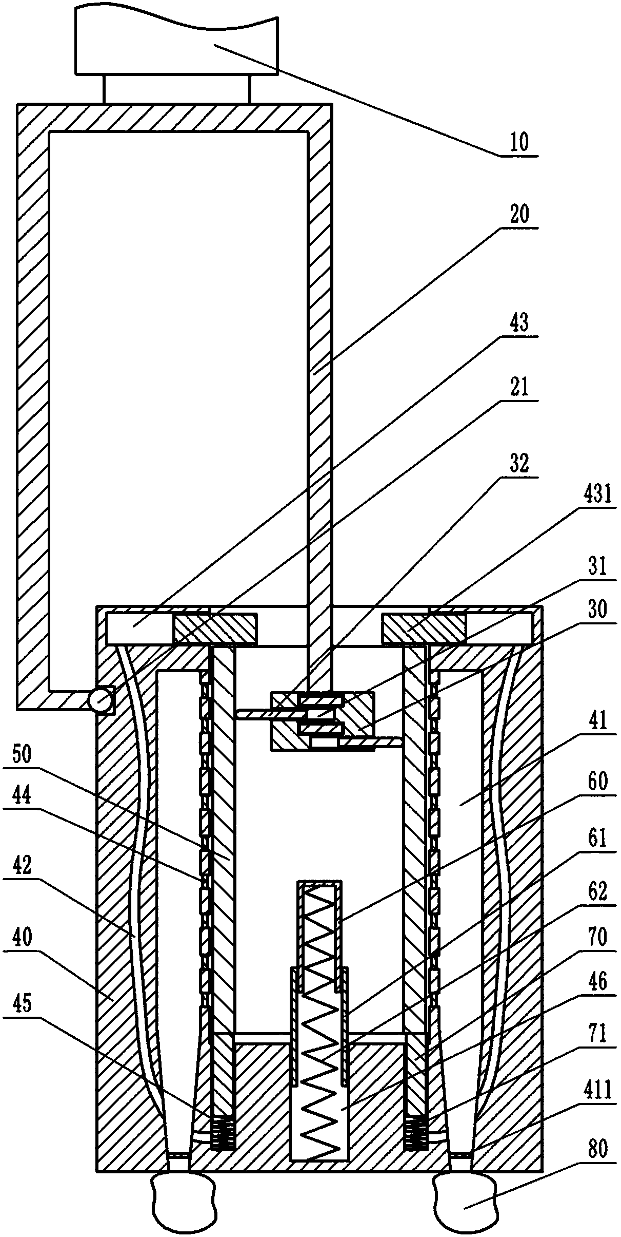
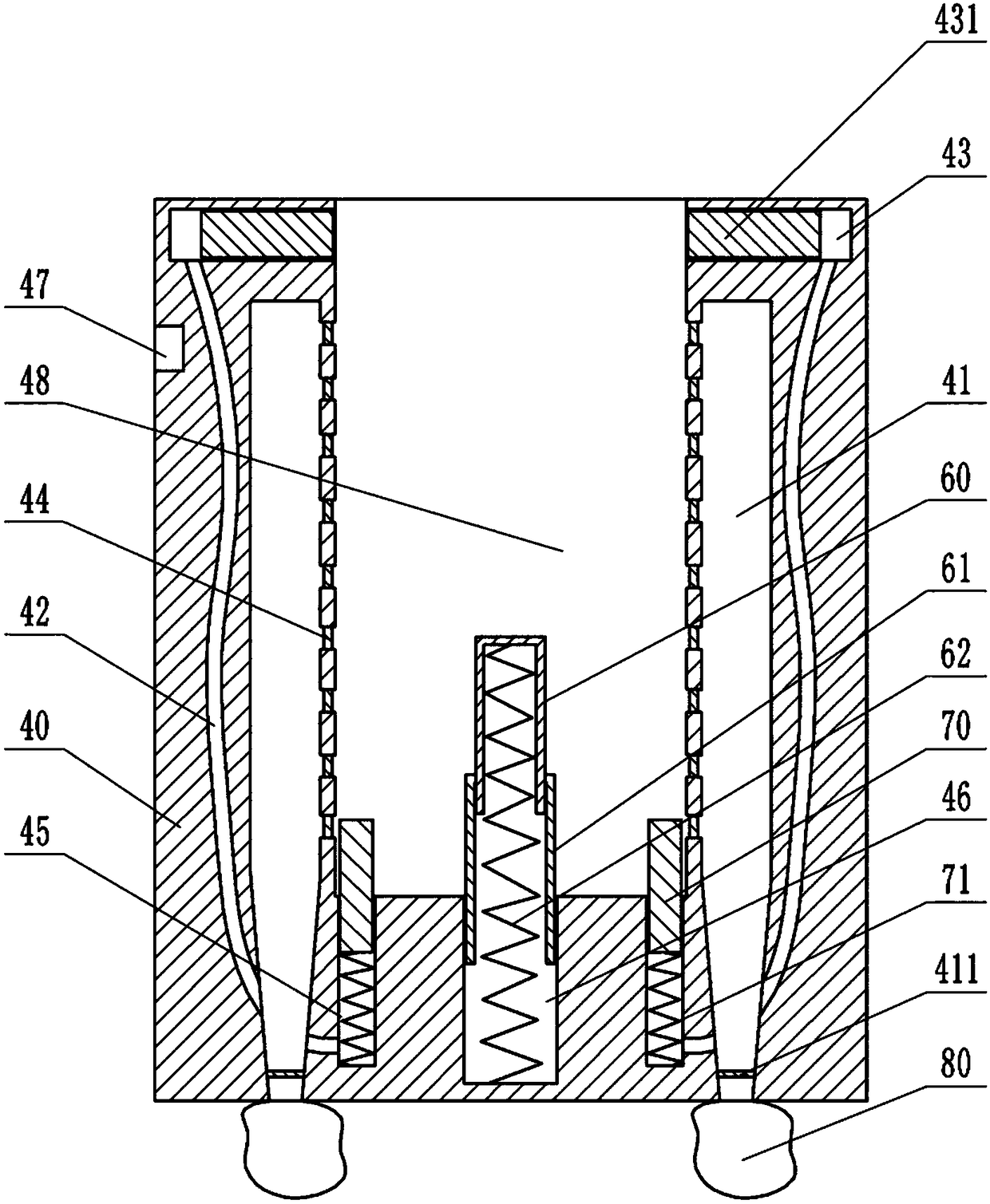
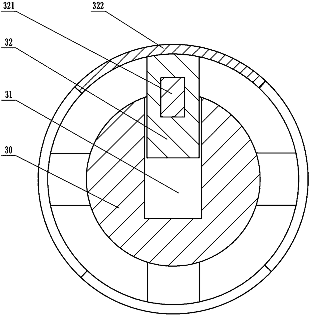
[0023] Instructions attached Figures 1 to 3 The reference signs in include: hydraulic cylinder 10, push rod 20, ball 21, grinding disc 30, card slot 31, extension block 32, magnet 321, grinding block 322, grinding cylinder 40, annular cavity 41, one-way door 411 , channel 42, strip groove 43, limit block 431, one-way valve 44, annular groove 45, chute 46, groove 47, cavity 48, part 50, inner cylinder 60, annular cylinder 61, second spring 62, the annular protrusion 70, the first spring 71, and the collection filter bag 80.

[0024] Such as figure 1 As shown, the parts grinding device includes a frame, a grinding unit, a connecting unit and a power unit, the connecting unit is a push rod 20 in the shape of a “冂”, the power unit can be an air cylinder or a hydraulic cylinder 10, and the hydraulic cylinder is selected in this embodiment 10. The push rod 20 is fixed on th...


PUM


Abstract

The invention belongs to the technical field of machining equipment, and particularly discloses a part polishing device. The part polishing device comprises a rack, a polishing unit, a connecting unitand a power unit. The polishing unit comprises a polishing disc and a polishing barrel. A concave cavity and an annular cavity are formed in the polishing barrel. An annular groove is formed in the bottom of the polishing barrel. The annular groove is internally and slidably connected with an annular protrusion. A strip-shaped groove is formed in the polishing barrel. The strip-shaped groove is internally and slidably connected with a limiting block. A channel is connected to the position between the strip-shaped groove and the annular groove. A sliding groove is formed in the bottom of the polishing barrel. The sliding groove is internally and slidably connected with a sliding rod. The polishing barrel is internally provided with a plurality of electromagnets. A plurality of clamping grooves are formed in the polishing disc. The clamping grooves are internally and slidably connected with stretching-out blocks. The stretching-out blocks are provided with magnets and polishing blocks.A spiral groove is formed in the outer wall of the polishing barrel. The connecting unit comprises an n-shaped push rod. The polishing disc is fixed to one end of the push rod. The other end of the push rod is connected with a transverse rod. By using the polishing device, the inner surfaces and the outer surfaces of pipe-type parts can be polished simultaneously, and the efficiency is high.

Description

technical field [0001] The invention belongs to the technical field of mechanical processing equipment, and in particular relates to a parts grinding device. Background technique [0002] In the field of mechanical processing, after the rough machining of the parts, the surface of the parts is often very rough and there are many burrs. The burrs refer to the extremely fine microscopic metal particles on the surface of the parts. Chips formed during machining. When the parts are finished, it is necessary to remove the burrs on the surface of the parts and smooth the surface of the parts to improve the precision of the parts. [0003] In the prior art, the manual method is usually used to remove the burrs on the surface of the part by using a file or a hammer. This method has low work efficiency and high work intensity. For the deburring of pipe parts, it is usually necessary to polish the inner and outer surfaces. When grinding the outer surface, fix the pipe by fixing the ...

Claims


Application Information

Patent Timeline
Patent Type & Authority Applications(China)
IPC IPC(8): B24B9/04B24B41/02B24B41/06B24B41/00B24B27/00
CPCB24B9/04B24B27/0076B24B41/00B24B41/02B24B41/06
Inventor 王健
Owner 宁波鑫神泽汽车零部件有限公司
Why Eureka
Try Eureka