Sprinkler and washing machine
A technology of a spray device and a washing machine, applied in the field of washing machines, can solve the problems of small contact area of moist and hot air, increase user cost, waste water, time and electricity, etc., and achieve good diversion effect, improve utilization rate, and increase the effect of residence time.
- Summary
- Abstract
- Description
- Claims
- Application Information
AI Technical Summary
Problems solved by technology
Method used
Image
Examples
Embodiment 1
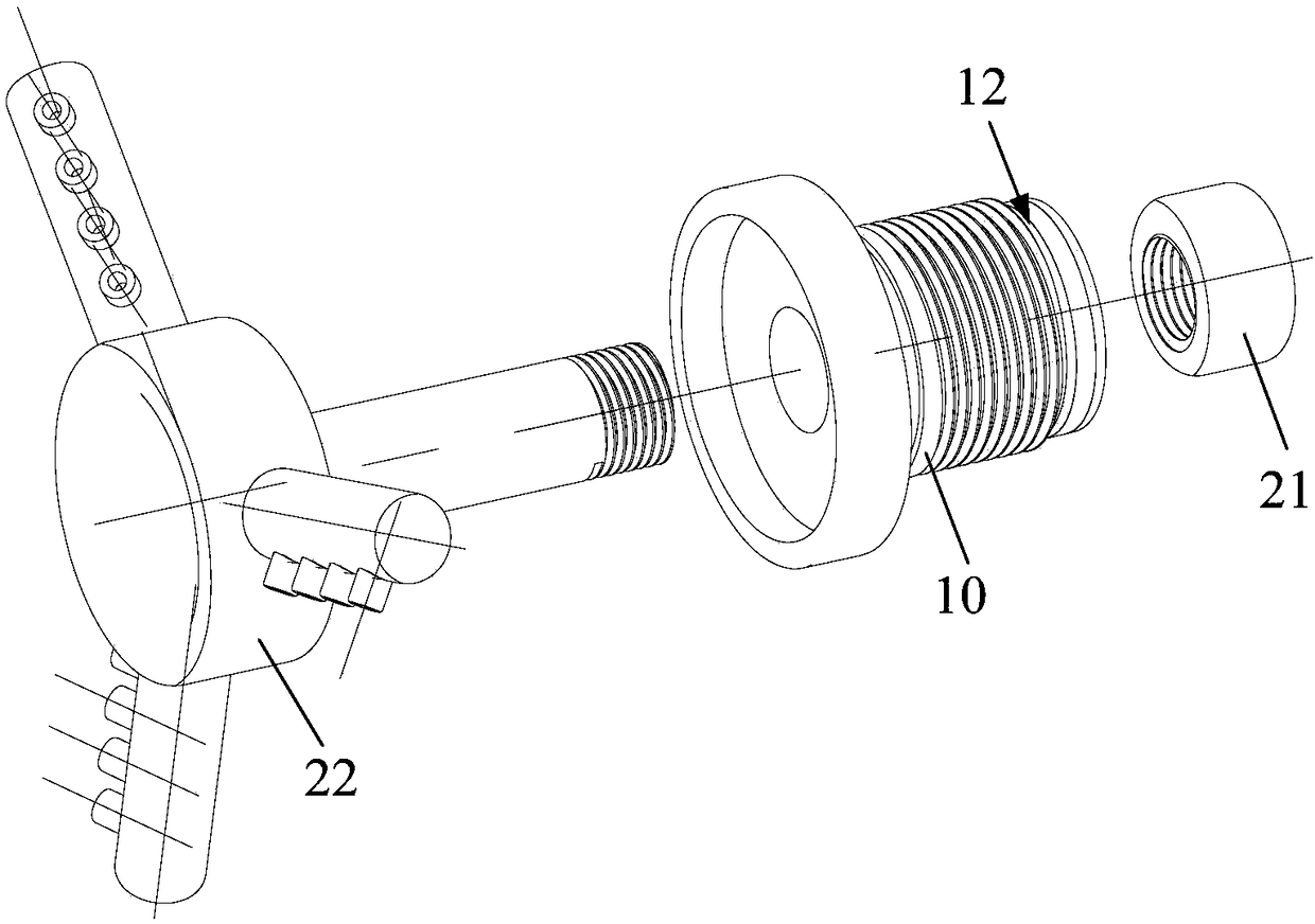
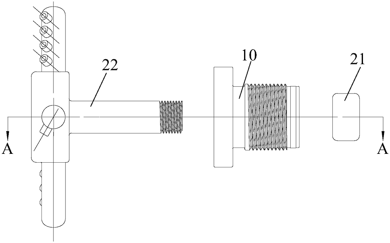
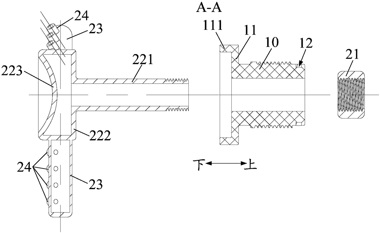
[0085] The rotary spray head 20 includes: a stopper and a spray head main body 22, such as Figure 1 to Figure 3 shown. Wherein, the limiting member is supported on the top of the nozzle base 10; the nozzle base 10 is hollow inside, and the upper end of the nozzle body 22 passes through the nozzle base 10 and is fixedly connected with the limiting member, as Figure 4 to Figure 7 As shown, and can rotate relative to the shower head base 10 , the lower end of the shower head body 22 is provided with a nozzle 24 .
[0086] The nozzle base 10 is hollow inside, forming a cylindrical structure with both ends open; The function cannot enter the interior of the nozzle base 10; the upper end of the nozzle body 22 passes through the nozzle base 10 and is fixedly connected with the stopper, realizing the assembly of the rotating nozzle 20 and the nozzle base 10; and the nozzle body 22 can be opposite to the nozzle base. 10 rotates, so it can drive the stopper to rotate synchronously, ...
Embodiment 2
[0101] The difference with Embodiment 1 is that: on the basis of Embodiment 1, a connecting pipe 23 is provided on the outer wall of the rotary spray head 20, such as Figure 1 to Figure 3 As shown, one end of the connecting pipe 23 communicates with the inner space of the rotary spray head 20, and the other end is closed and arranged. The nozzle 24 is arranged on the connecting pipe 23 and communicates with the connecting pipe 23, as Figure 5 to Figure 7 shown.
[0102] Connecting pipe 23 is set on the outer wall of rotating shower head 20, and connecting pipe 23 has increased the radial dimension of rotating shower head 20, because one end of connecting pipe 23 communicates with the inner space of rotating shower head 20, and the other end is closed, thereby nozzle 24 Set on the connecting pipe 23, the condensed water needs to enter the nozzle 24 through the connecting pipe 23 and then spray out. This has not only further increased the spraying radius of the spraying device ...
Embodiment 3
[0118] The difference with the second embodiment is that: on the basis of the second embodiment, a sealing groove 12 is further provided on the outer wall of the nozzle base 10, such as Figure 13 with Figure 18 As shown, the spraying device 1 further includes a seal 30 installed in the sealing groove 12 for sealing the gap between the spray head base 10 and the drying tunnel 2 .
[0119] Sealing groove 12 is set on the outer wall of shower head base 10, and sealing member 30 (such as rubber sealing ring) is installed in sealing groove 12, then sealing member 30 can seal the gap between shower head base 10 and drying channel 2, guarantees The sealing reliability between the spraying device 1 and the drying tunnel 2 is improved, and water leakage between the spraying device 1 and the drying tunnel 2 is prevented, causing other components in the washing machine to be adversely affected.
[0120] In some embodiments of the present invention, the connecting portion is an externa...
PUM
 Abstract
Description
Claims
Application Information
 - R&D
- Intellectual Property
- Life Sciences
- Materials
- Tech Scout
- Unparalleled Data Quality
- Higher Quality Content
- 60% Fewer Hallucinations
Browse by: Latest US Patents, China's latest patents, Technical Efficacy Thesaurus, Application Domain, Technology Topic, Popular Technical Reports.
© 2025 PatSnap. All rights reserved.Legal|Privacy policy|Modern Slavery Act Transparency Statement|Sitemap|About US| Contact US: help@patsnap.com


