Spraying device

Inactive Publication Date: 2007-07-12
IND TECH RES INST
View PDF26 Cites 11 Cited by
  • Summary
  • Abstract
  • Description
  • Claims
  • Application Information

AI Technical Summary

Benefits of technology

[0023]In comparison to the prior art, the present invention proposes a spraying device having a planar nozzle plate. The geometric shape of the exit end of more than one nozzle aperture of the nozzle plate is designed as a thin plate which allows the liquid to be expelled from the nozzle aperture via a tilting predetermined angel. Such geometric design and the distribution of the nozzle apertures of the nozzle plate are able to achieve a divergent spraying effect when the nozzle plate is actuated by the actuator. Also, a spraying direction of a liquid droplet after the liquid is atomized can be controlled, such that the liquid droplets are expelled in a converging manner or in a diverging manner for increasing a spraying area. Thus, problems facing the prior art, including atomized liquid droplets being expelled in a perpendicular direction, an atomizing area limited to a distribution area of a nozzle aperture, and droplet accumulation due to convergent spraying, can be solved. Therefore, the present invention can be applied to atomization of a liquid in biomedical science, such that accumulation of atomized liquid droplets can be prevented to improve the homogeneity of the atomized liquid droplets. Also, it can be applied to a cooling system, such that a cooling mechanism can be operated effectively and consistently by increasing an atomizing area. Furthermore, it can also be applied to a drug delive

Problems solved by technology

Therefore, an atomizing area is typically small as a result, which adversely affects the atomization effect.
Furthermore, due to the extreme narrowness of the atomizing area, atomized liquid droplets can collide with each other and accumulate.
This not only increases the size of the atomized liquid droplets but also causes a poor atomization effect.
Moreover, if the atomizing area is to be modified, the distribution area of the nozzle apertures has to be modified correspondingly or the actuating frequency has to be modulated correspondingly, thus inevitably increasing the volume of the system.
Additionally, large-scale actuation requires a higher resonance form and therefore consumes more energy.
Therefore, the forgoing technique does not satisfy the practical demand as it consumes more energy and does not meet the miniaturization requirement due to its bulkiness.
However, as the fabrication method of the nozzle plate is very complicated, the patent is cost-ineffective.
Therefore, the patent fails to compete with others in mass production, and thus cannot meet the requirement for the market.
Despite an increase in the atomizing area, an increase in the spraying area of the nozzle apertures entails using different piezoel

Method used


Image

  • Spraying device
  • Spraying device
  • Spraying device

Examples


Example

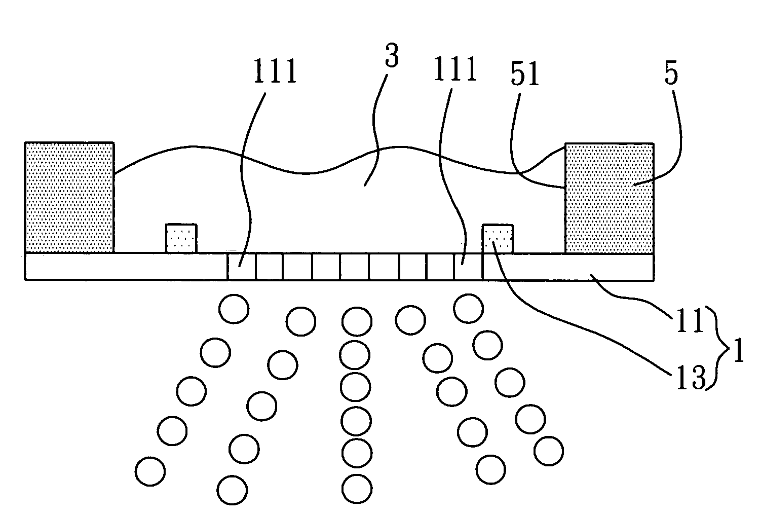
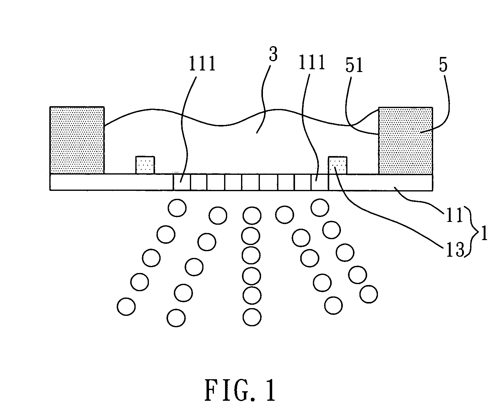
[0036]The following embodiment only serves to provide further description for the present invention with no intent to limit the scope of the invention. An important point to note is that only basic structures of a spraying device are illustrated in the following embodiments. The spraying device can be provided with additional elements according to an atomizing system, such as a drug delivery system in a spraying device, a fuel-injection atomizing system, and a heat dissipating cooling system or other systems requiring sufficient liquid atomization, and thus is not limited by what described in the following embodiments.

[0037]An important point to note is that these drawings are simplified schematic diagrams, and thus only structures relevant to the present invention are illustrated. Also, these structures are not drawn according to actual amounts, shapes and dimensions. Actually, quantity, shape and dimensions belong to a matter of design and the arrangements of the structures may be...


PUM


Abstract

A spraying device for atomizing a liquid is proposed. The spraying device includes a nozzle plate and an actuator. The nozzle plate is provided with a plurality of nozzle apertures. Each of the nozzle apertures includes an entry end for the liquid to enter and an exit end for the liquid to exit. The entry end and the exit end of at least one of the nozzle apertures are asymmetrical structures. The actuator is integrated with the nozzle plate to actuate atomization of the liquid. The spraying direction of a liquid droplet after the liquid is atomized can be controlled by modifying the shape of the exit end of the nozzle aperture.

Description

FIELD OF THE INVENTION[0001]The present invention relates to a liquid atomizing technique, and more particularly, to a spraying device.BACKGROUND OF THE INVENTION[0002]With rapid advances in technology, the scope of application of technology that utilizes an atomizing system to carry out liquid atomization is becoming broader. The atomization principle has been used in the applications such as a spraying device of a drug delivery system utilized in biomedical science, a fuel-injection atomizing system required for providing engine combustion, and a beat dissipating cooling system that achieves a cooling effect by means of a liquid phase-change. The relevant techniques have been disclosed in the U.S. Pat. No. 4,465,234, the U.S. Pat. No. 4,605,167, the U.S. Pat. No. 6,089,698, the U.S. Pat. No. 6,235,177, the U.S. Pat. No. 6,629,646, Taiwanese Patent No. 407529, Taiwanese Patent No. 449486, Taiwanese Patent No. 503129, Taiwanese Patent No. 506855, Taiwanese Patent No. 562704, and Tai...

Claims


Application Information

Patent Timeline
IPC IPC(8): B05B1/34A62C31/02B05B1/00
CPCB05B17/0646B05B1/02
Inventor WU, CHOU-LINHUANG, CHI-MINGLU, CHUN-FUCHEN, CHUN-JUNG
Owner IND TECH RES INST
Why Eureka
Try Eureka