Reducing wheel forces on a field surface

a field surface and wheel technology, applied in the field of reducing wheel forces on the field surface, can solve the problems of increasing the space required for the placement of each front wheel, reducing the productivity of soil, and reducing the space available for the frame wheel, so as to reduce the force of the wheel, reduce the compaction, and reduce the effect of soil productivity loss

Active Publication Date: 2018-04-03
BOURGAULT INDS
View PDF14 Cites 1 Cited by
  • Summary
  • Abstract
  • Description
  • Claims
  • Application Information

AI Technical Summary

Benefits of technology

[0013]In a first embodiment the present disclosure provides a method of reducing implement wheel forces on an agricultural field surface. The method comprises providing an agricultural implement comprising an implement frame mounted on a plurality of frame wheels for travel in an operating travel direction and a plurality of ground engaging tools mounted on the implement frame, and wherein the frame wheels support the implement frame and ground engaging tools in a desired orientation with respect to the field surface; movably connecting a plurality of support arms to the implement frame and rotatably mounting a support wheel to a wheel end of each support arm; towing the agricultural implement along the field surface with the ground engaging tools penetrating the field surface to a desired working depth, wherein the ground engaging tools exert an upward tool force on the implement frame that is less than a downward force exerted by a frame weight of the implement frame; exerting a support bias force on each support arm to push the support wheel against the field surface and to correspondingly urge the implement frame upward with respect to the support wheel to transfer a supported frame weight from the implement frame to the support wheels, such that an unsupported frame weight is carried on the frame wheels; selecting the support bias forces such that the unsupported frame weight is greater than the upward tool force.
[0015]The present disclosure provides a system and method for reducing wheel forces exerted on agricultural field surfaces, thereby reducing compaction and loss of soil productivity. In the present disclosure the weight of the implement frame is spread over an increased number of wheels, thus reducing the weight on each wheel. In addition to reducing compaction, in very soft field surfaces the tendency of the frame wheels to sink into soft ground is reduced.

Problems solved by technology

Positioning the frame wheels in the middle of the frame with the requirement that the ground engaging tools be evenly spaced means that the space available for frame wheels is limited.
The requirement that the front wheels pivot about a vertical axis significantly increases the space required for placement of each front wheel.
In hard soil conditions, typical ground engaging tools, such as disc type furrow openers of an air seeder, may require a considerable downward force applied thereto to force them to penetrate the ground.
Conversely in softer soils, little downward force may be required to cause the ground engaging tools to penetrate the soil with the result that most of the weight of the frame is carried on the frame wheels.
Where the ground is very soft the frame wheels may sink into the soil surface, causing the ground engaging tools to penetrate deeper into the soil and thus adversely affecting the desired working depth and increasing the draft forces required to tow the implement, increasing fuel costs.
In extreme cases the frame wheels may sink to such an extent that the implement becomes stuck.
Even where the soil is not so soft as to cause the frame wheels to sink, the increased weight on the frame wheels can cause compaction of the soil and adversely affect the productivity of the soil.

Method used


Image

  • Reducing wheel forces on a field surface
  • Reducing wheel forces on a field surface
  • Reducing wheel forces on a field surface

Examples


Embodiment Construction

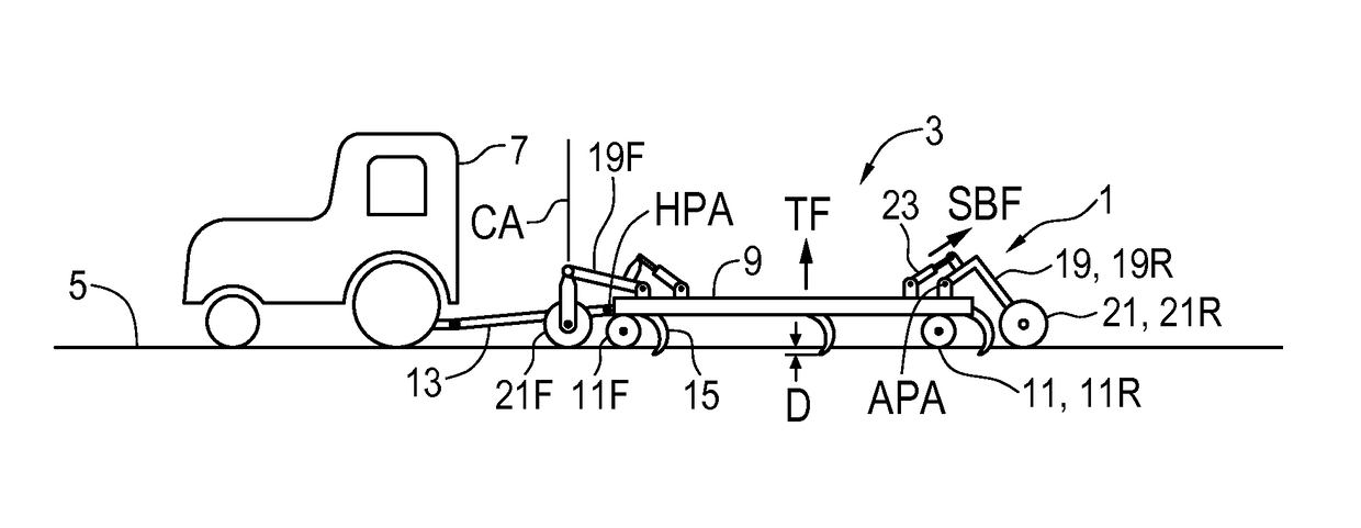
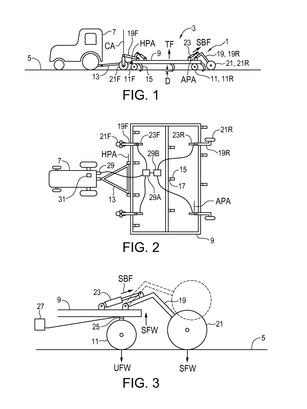
[0027]FIGS. 1 and 2 schematically illustrate an embodiment of a system 1 of the present disclosure for reducing implement wheel forces on an agricultural field surface. An agricultural implement 3 is connected to a tractor 7 for towing along the field surface 5 and the implement 3 comprises an implement frame 9 mounted on a plurality of frame wheels 11 for travel in an operating travel direction T along the field surface 5. The illustrated implement 3 is of the floating hitch type with front and rear frame wheels 11 and a hitch 13 pivotally attached to the implement frame 9 about a hitch pivot axis HPA. As is known in the art the front frame wheels 11F are caster wheels.

[0028]A plurality of ground engaging tools 15 are mounted on the implement frame 9, and the frame wheels 11 support the implement frame 9 and ground engaging tools 15 in a desired orientation with respect to the field surface 5, with the implement frame 9 substantially parallel to the field surface 5. A tool control ...


PUM


Abstract

A system for reducing implement wheel forces on a field surface has an agricultural implement with a frame mounted on frame wheels and ground engaging tools mounted on the frame. When the ground engaging tools move down to penetrate the field surface they exert an upward tool force on the frame. Support arms are movably connected to the implement frame and a support wheel is rotatably mounted to each support arm. A support bias element exerts a support bias force on each support arm to force the support wheel against the field surface and to correspondingly force the implement frame upward, transferring a supported frame weight from the implement frame to the support wheels, such that an unsupported frame weight is carried on the frame wheels. A bias control varies the support bias forces to maintain the unsupported frame weight at a level greater than the upward tool force.

Description

[0001]This disclosure relates to the field of agricultural implements and in particular provides a system and method for reducing wheel forces exerted on agricultural field surfaces.BACKGROUND[0002]A typical towed agricultural implement has a frame supported on frame wheels with a hitch extending forward from the frame for connection to a tractor for towing in an operating travel direction, and a plurality of ground engaging tools mounted on the frame. The frame wheels support the frame in an orientation parallel to the soil surface such that each ground engaging tool penetrates the soil to the same depth. In order to allow larger modern agricultural implements to follow varying ground contours the implement frame will typically include a plurality of wing frames connected at horizontal pivot axes oriented parallel to the operating travel direction. The frame wheels must be located and configured to support each wing frame in an orientation horizontal to the surface of the soil unde...

Claims


Application Information

Patent Timeline
Patent Type & Authority Patents(United States)
IPC IPC(8): A01B63/14
CPCA01B63/145
Inventor JAGOW, SCOTKLENZ, ROBERTARGUIN, ADEN
Owner BOURGAULT INDS
Why Eureka
Try Eureka