Lifter

Active Publication Date: 2018-04-10
DAIFUKU CO LTD
View PDF9 Cites 1 Cited by
  • Summary
  • Abstract
  • Description
  • Claims
  • Application Information

AI Technical Summary

Benefits of technology

[0003]The known lifters are configured to elevate / lower the workpiece support base by making the pair of right and left crosslink mechanisms operate to rise and collapse by means of the elevation / lowering drive chains as described above. While sudden lowering, that is, falling of the workpiece support base can be deterred by the fall prevention means during elevation of the workpiece support base, when the elevation / lowering drive chains are driven in a direction to lower the workpiece support base, the ratchet pawls of the fall prevention means are switched to and held in the unengaged orientations by the actuators and therefore when the elevation / lowering drive chains break during the lowering of the workpiece support base, the fall prevention means will not be effective and this may lead to a serious accident.

Problems solved by technology

While sudden lowering, that is, falling of the workpiece support base can be deterred by the fall prevention means during elevation of the workpiece support base, when the elevation / lowering drive chains are driven in a direction to lower the workpiece support base, the ratchet pawls of the fall prevention means are switched to and held in the unengaged orientations by the actuators and therefore when the elevation / lowering drive chains break during the lowering of the workpiece support base, the fall prevention means will not be effective and this may lead to a serious accident.

Method used


Image

  • Lifter
  • Lifter
  • Lifter

Examples


Embodiment Construction

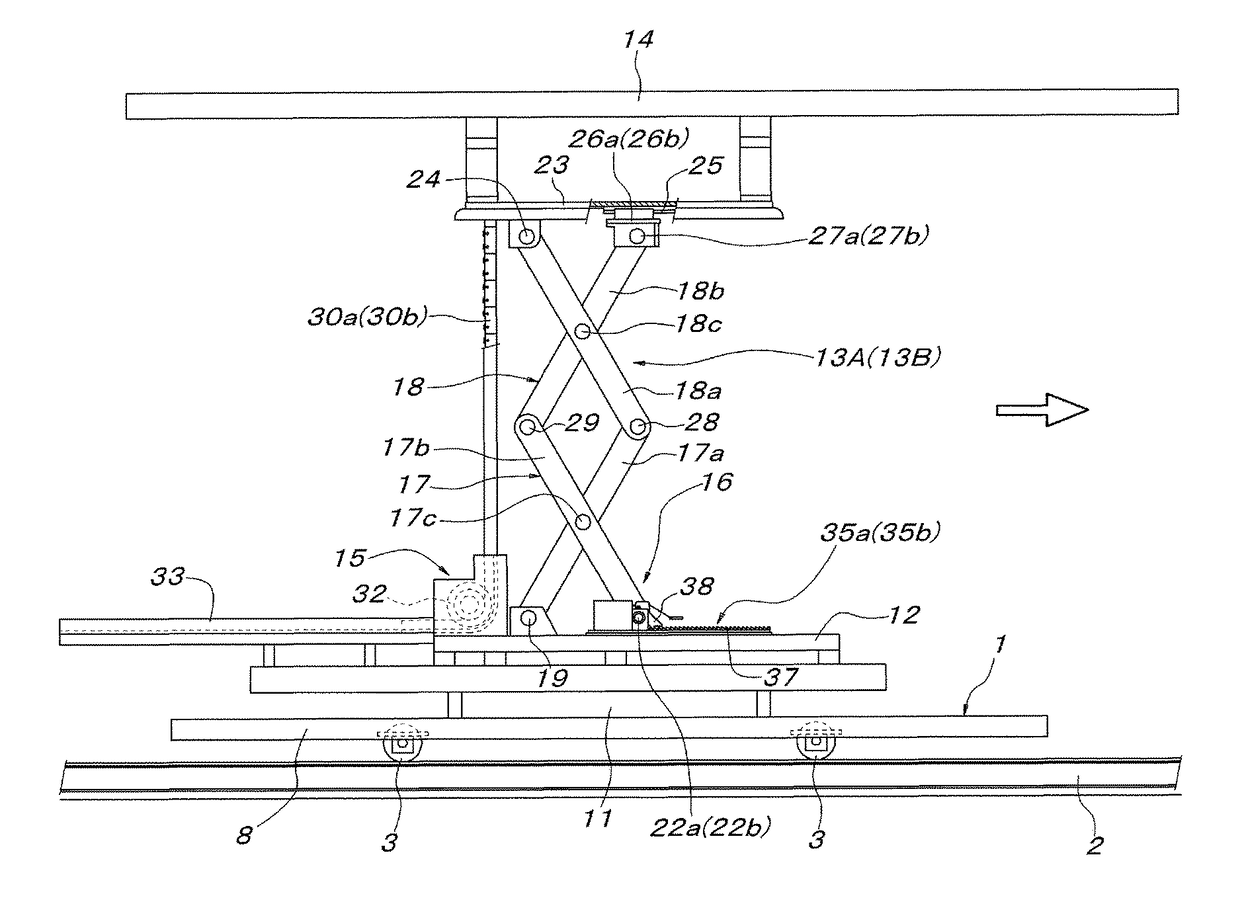
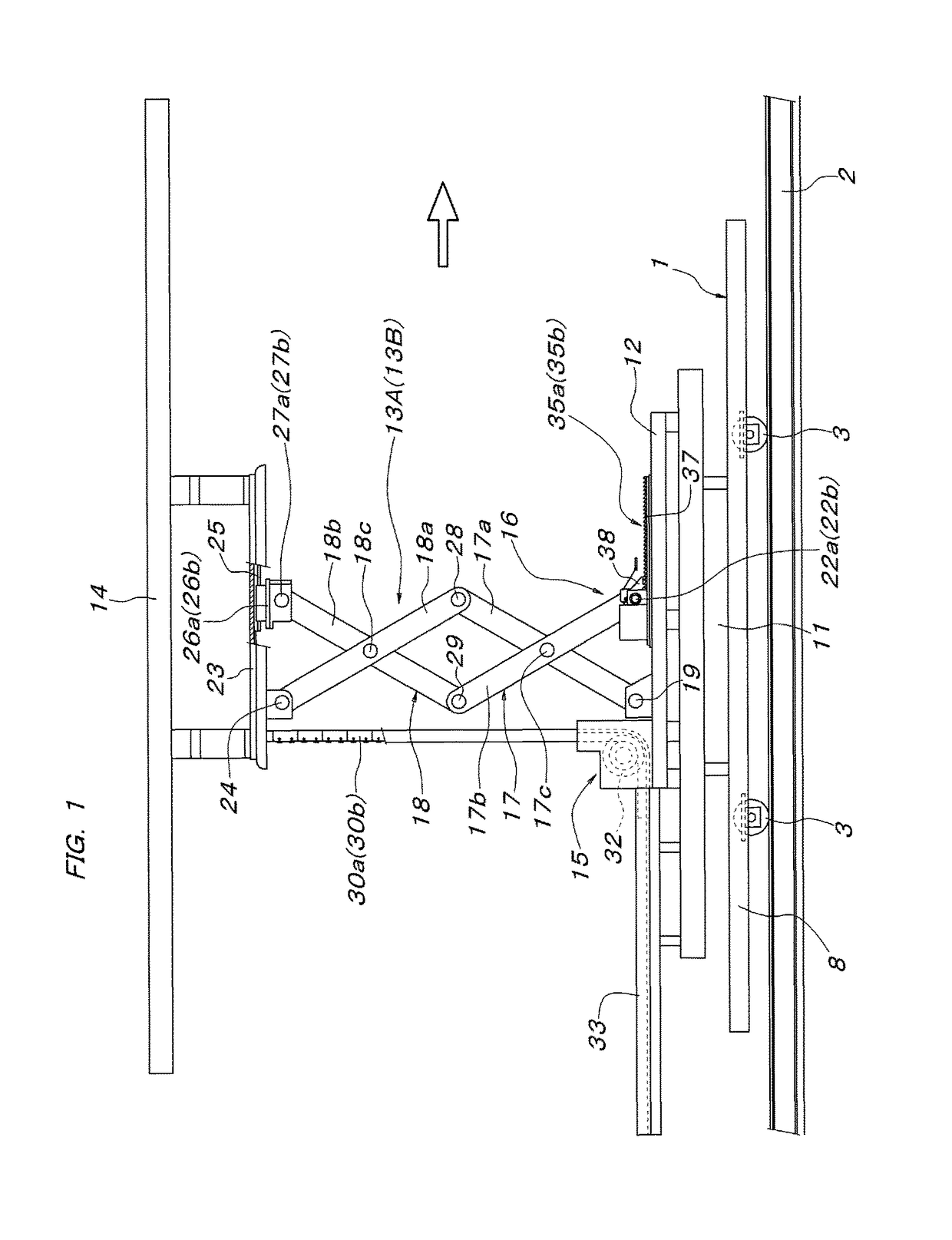
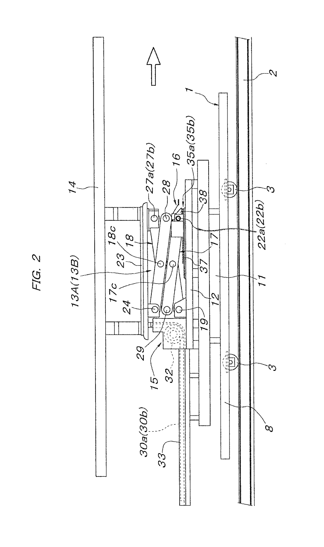
[0020]In FIG. 1 to FIG. 4, a conveying traveling body 1 includes two front and rear pairs of right and left wheels 3 rolling on a pair of right and left supporting guide rails 2 laid along a travel path of the conveying traveling body 1. A pair of front and rear steady rollers 5 fitting in right-left lateral direction steady guide rails 4 are laid at an outer side of, and so as to be in parallel to, a guide rail 2 at one side, and a pair of front and rear vertical motion preventing rollers 7 fitting in a vertical motion preventing guide rail 6 are laid at an inner side of, and so as to be in parallel to, the guide rail 2 at one side. The conveying traveling body 1 is thereby configured to be capable of traveling along the fixed travel path. A travel drive means of the conveying traveling body 1 may be of any configuration. For example, friction drive means 10 may be used as indicated by virtual lines in FIG. 4. The friction drive means 10 can include friction drive wheels 9, which a...


PUM


Abstract

A lifter is provided with operating levers, which, against driving forces of actuators that switch the ratchet pawls to unengaged orientations, switch the ratchet pawls to engaged orientations of being engaged with ratchet gears, is provided with a link mechanism, which, when a workpiece support base is being lowered by collapsing motions of a pair of right and left crosslink mechanisms supporting the workpiece support base and a difference arises in movement amounts of movable support shafts at lower end sides of the respective crosslink mechanisms, converts the movement amount difference to an operating force of the operating lever at the larger movement amount side, and is such that by the operating lever at one side being driven by the link mechanism, the operating lever switches the ratchet pawl at the larger movement amount side to the engaged orientation.

Description

FIELD OF THE INVENTION[0001]The present invention relates to a lifter installed on a conveying traveling body, etc., and utilized as a means to change a support height of a conveyed object.BACKGROUND OF THE INVENTION[0002]Known lifters for conveying devices can include a workpiece support base, vertically movably supported on a base via a pair of right and left crosslink mechanisms, an elevation / lowering drive means, elevatingly and loweringly driving the workpiece support base, and a pair of right and left fall prevention means, juxtaposed to the respective crosslink mechanisms. The fall prevention means can include a pair of right and left ratchet gears, fixed to movement path flanks of movable support shafts, which are capable of forward / reverse movement, at the base sides of the respective crosslinks. The fall prevention means can also include a pair of right and left ratchet pawls, moving forward and in reverse in interlock with the respective movable support shafts and being e...

Claims


Application Information

Patent Timeline
Patent Type & Authority Patents(United States)
IPC IPC(8): B66F17/00B66F3/22B65G35/06
CPCB66F17/00B66F3/22B65G35/06B65G2207/40B66F7/0633B66F7/28B66F3/06B66F7/0666
Inventor OOE, MASAHIRO
Owner DAIFUKU CO LTD
Why Eureka
Try Eureka