Methods for assembling LED connector board

a technology of led connectors and connector boards, applied in the direction of printed circuit assembling, high current circuit adaptations, printed circuit aspects, etc., can solve the problems of creating obstruction and interference to led lights, and the height of any additional height can be significant, so as to reduce the height introduced, minimize the height, and maximize the dispersion and distribution of led lights

Active Publication Date: 2018-04-10
AMERLUX
View PDF7 Cites 2 Cited by
  • Summary
  • Abstract
  • Description
  • Claims
  • Application Information

AI Technical Summary

Benefits of technology

[0005]To maximize LED light dispersion and distribution, the profile of LED connector board assemblies can be optimized so as to have minimal obstruction and interference to LED light elements. Connectors for LED boards, while effective in connecting the LED board to electrical wires, can create obstruction and interference to LED lights by stacking additional height to the profile of an LED board. Because LED lights are of minimal dimension, obstruction introduced by any additional height can be significant. As disclosed herein, metal track with an integrated recess can be used in an LED connector board assembly to accommodate an LED board connected to, for example, leaf spring connectors with extended integral insulating bosses or sleeves (if desired) for electrical wires, thus reducing height introduced by the connection between the LED board and the leaf spring connectors.
[0006]The assembly systems and methods can be provided with a metal track to which the LED board and connectors can be attached. The connectors of the present disclosure can be a set of leaf springs connectors attached to an injection molded base. The set of leaf spring connectors can be attached to the injection molded base (e.g., via integral molding, melting of the base around a portion of the leaf spring, adhesive, rivets, and the like) and the base in turn can be provided with curved wings or lateral protrusions extending from two opposite sides of the base. The metal track of the disclosed systems and methods can be provided with an integral recess that receives the injection molded base in which the recess can further be provided with notches on opposite sides of the recess that receive the curved wings of the injection molded base. The notches can be sized to match different sized wings / protrusions on the body so as to ensure a single proper installation to avoid mismatching polarity of conductors.
[0007]In one embodiment of the present disclosure, the injection molded base can be of rectangular shape with a top surface, a bottom surface, and a curved or ridged side, defining a minimal height for the base, running along and in between the top and the bottom surfaces. The injection molded base can be provided with a securing hole in the center of the base for connection to the LED board, via a securing element such as a screw. The injection molded base can be further provided with a plurality of wire openings situated diagonally across the top and bottom surfaces of the base. The injection molded base can also be provided with a set of curved wings or lateral protrusions along the length sides of the rectangular base. In a further embodiment, one of the curved wings can be of a length that is longer than the other, so as to facilitate correct installation to avoid mismatching of polarity.
[0009]In accordance with another aspect of the present disclosure, the injection molded base can be further provided with a set of wire insulating bosses extending from the bottom surface of the base. In another embodiment of the present disclosure, the insulating bosses can be provided diagonally across from each other on the bottom surface of the base and are matched in dimensions and locations to the two wire openings provided on the top and bottom surfaces of the base. The bosses define a conduit therethrough for passage of the conductors, and prevent conductive material in the conductors from contacting the metal track.

Problems solved by technology

Connectors for LED boards, while effective in connecting the LED board to electrical wires, can create obstruction and interference to LED lights by stacking additional height to the profile of an LED board.
Because LED lights are of minimal dimension, obstruction introduced by any additional height can be significant.

Method used


Image

  • Methods for assembling LED connector board
  • Methods for assembling LED connector board
  • Methods for assembling LED connector board

Examples


Embodiment Construction

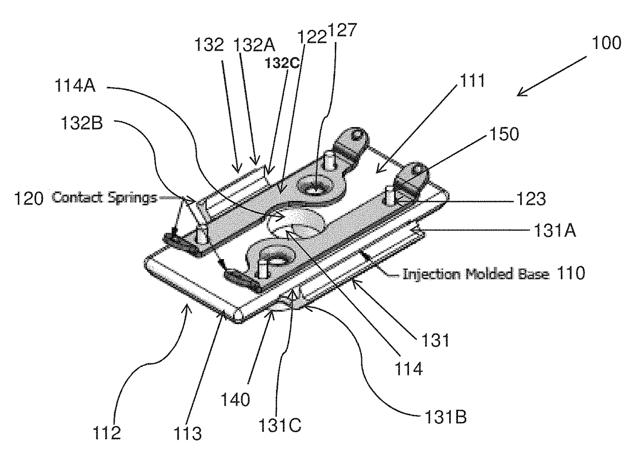
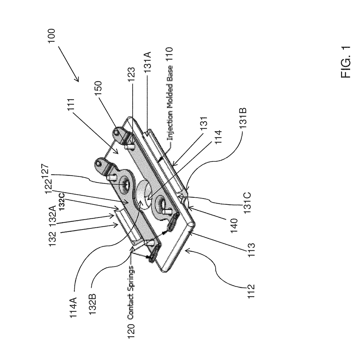
[0031]For purpose of explanation and illustration, and not limitation, an exemplary embodiment of an LED connector board assembly in accordance with the present disclosure is shown in FIG. 11, and is designated generally by reference number too. This exemplary embodiment is also depicted in the remaining figures.

[0032]Generally, a LED connector board assembly too of the present disclosure includes a set of leaf spring connectors 120, which can be made out of an electrically conductive material for connecting electrical wires 160 to an LED board 310, an injection molded base 110 to which spring connectors 120 can be attached, and a metal track 201 with an integrated recess 203 for accommodating the injection molded base 110 and upon which the LED board 310 can be attached.

[0033]As illustrated in FIG. 1, leaf spring connectors 120 can be attached to a top surface 111 of the injection molded base 110. Injection molded base 110 can be a three-dimensional rectangle with a top surface 111...


PUM

PropertyMeasurementUnit
light dispersionaaaaaaaaaa
heightaaaaaaaaaa
polarityaaaaaaaaaa

Abstract

Systems and methods for assembling an LED connector board wherein the assembly can be provided with a metal track with an integrated recess for receiving an injection molded base, onto which a set of leaf spring connectors with extended insulating bosses for electrical wires can be secured.

Description

CROSS-REFERENCE TO RELATED APPLICATION[0001]This patent application claims the benefit of priority to U.S. Provisional Patent Application Ser. No. 62 / 048,688, filed Sep. 10, 2014, the content of which is incorporated herein by reference in its entirety for any purpose whatsoever.FIELD[0002]The present disclosure relates to systems and methods for assembling LED connector boards.BACKGROUND[0003]LED connection systems are known. However, the current state of the art has certain shortcomings, as appreciated by Applicant as described herein. The present disclosure presents improvements over the state of the art.SUMMARY OF THE DISCLOSURE[0004]LED lighting systems and methods for assembling LED connector boards are disclosed herein.[0005]To maximize LED light dispersion and distribution, the profile of LED connector board assemblies can be optimized so as to have minimal obstruction and interference to LED light elements. Connectors for LED boards, while effective in connecting the LED bo...

Claims


Application Information

Patent Timeline
Patent Type & Authority Patents(United States)
IPC IPC(8): H05K3/30H01R4/02H05K1/02
CPCH05K3/30H01R4/023H05K1/0265Y10T29/49126H05K2201/10106H05K2201/10272Y10T29/4913H05K2201/09118
Inventor LESHNIAK, ITAISHAH, PARESHWALSH, JONATHAN
Owner AMERLUX
Why Eureka
Try Eureka