Image tagging device

a tagging device and image technology, applied in the field of image tagging devices, can solve the problems of a large number of steps and a lot of manpower, and achieve the effect of improving the efficiency of the tagging operation of workers

Active Publication Date: 2018-05-08
PANASONIC INTELLECTUAL PROPERTY CORP OF AMERICA
View PDF15 Cites 0 Cited by
  • Summary
  • Abstract
  • Description
  • Claims
  • Application Information

AI Technical Summary

Benefits of technology

[0009]According to the aspect, a worker can find an image of an object to be recognized in an operation request image, cut out an image region including the image of the object, and tag the image region. It is therefore possible to achieve an improvement in efficiency of a worker's tagging operation in addition to protection of privacy of a human in the operation request image.

Problems solved by technology

This requires a lot of manpower and a large number of steps.

Method used


Image

  • Image tagging device
  • Image tagging device
  • Image tagging device

Examples


embodiment

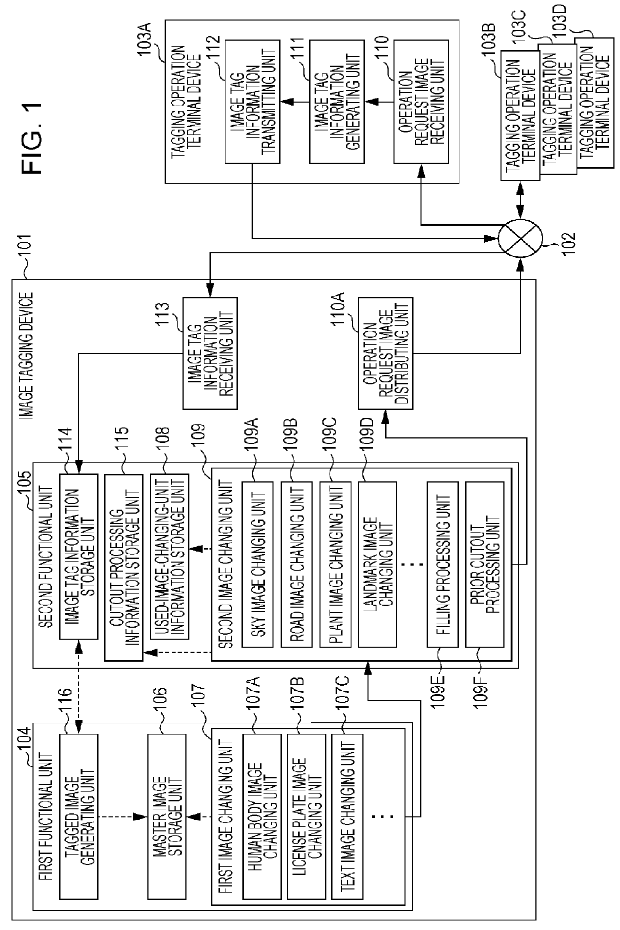
[0115]In the present embodiment, the image tagging device 101 for generating a tagged image of a road sign (e.g., a warning sign, a regulatory sign, or an indication sign) is described as an example with reference to FIG. 1. FIG. 11 illustrates a processing flow of the image tagging device 101 in the present embodiment.

[0116]The image tagging device 101 and the tagging operation terminal devices 103A through 103D are connected over the network 102 and transmit and receive data over the network 102.

[0117]The image tagging device 101 includes a first functional unit 104, a second functional unit 105, an operation request image distributing unit 110A, and an image tag information receiving unit 113.

[0118]As for a hardware configuration, the image tagging device 101 includes, for example, a processor, a memory, and the like (not illustrated). A program is, for example, stored in the memory. The program is, for example, a program that causes at least one of the first functional unit 104,...


PUM


Abstract

Provided is an image tagging device including: a first functional unit in which an image including an object that is a target of privacy protection is stored and that removes privacy information by changing part of the master image; a second functional unit that acquires the changed image from the first functional unit and changes a region image of an object that is not to be tagged in the first image; a function that distributes the changed image from the second functional unit to a tagging operation terminal device and receives image tag information from the tagging operation terminal device over a network; and a tagged image generator that generates a tagged image on the basis of the master image and the image tag information. This makes it possible to collect tagged images while achieving both privacy protection and an improvement in efficiency of a tagging operation.

Description

BACKGROUND[0001]1. Technical Field[0002]The present disclosure relates to an image tagging device utilizing a network represented by the Internet.[0003]2. Description of the Related Art[0004]In recent years, general object recognition based on a learning technique using a neural network called Deep Learning has been exhibiting high performance and attracting attention.[0005]However, in order to achieve high recognition performance in general object recognition based on Deep Learning, it is necessary to perform learning processing of a large number of images, as the learning subjects, with which the name, kind, or the like of an object to be recognized is associated as a tag. Note that it is desirable that the tagged images be images in which the object indicated by the tag is located at the center or occupies a large portion.[0006]In general, it is necessary to prepare approximately ten thousand tagged images, as the learning subjects, to achieve high recognition performance. This r...

Claims


Application Information

Patent Timeline
Patent Type & Authority Patents(United States)
IPC IPC(8): G06F21/00G06F21/62G06N3/08G06F21/60G06K9/00
CPCG06F21/602G06F21/6254G06N3/08G06K9/00664G06K9/00228G06V40/161G06V20/10
Inventor TAKAHASHI, MASAKITSUKIZAWA, SOTAROISHII, YASUNORIHAGAWA, REIKO
Owner PANASONIC INTELLECTUAL PROPERTY CORP OF AMERICA
Why Eureka
Try Eureka