Embedded audio system in distributed acoustic sources

a technology of distributed acoustic sources and embedded audio, applied in the field of embedded audio systems, can solve the problems of difficult to achieve optimal worker efficiency, difficult to effectively cover the sound of masking, and public spaces are often plagued by environmental noise, so as to reduce the need for notch filters, suppress room mode resonance, and suppress feedback amplification gain

Active Publication Date: 2013-12-31
KATZ ROBERT
View PDF16 Cites 0 Cited by
  • Summary
  • Abstract
  • Description
  • Claims
  • Application Information

AI Technical Summary

Benefits of technology

[0012]It is therefore an objective of the present invention to provide a system and a method for improving the acoustic performance of a building interior such as but not limited to an open office plan, exhibition space or other public or living space. A further objective includes improving the overall worker efficiency within a workstation by utilization of otherwise non acoustic elements and surfaces of the built environment such as walls, ceilings, floors, windows, columns and finished case goods such as workstations, furniture, partitions, cabinets, whiteboards, tables and other commonly available furnishings within an interior environment to radiate sound by means of acoustically driving the aforementioned.
[0013]Another objective of the invention is to provide a means of optimizing the acoustic performance of the aforementioned traditionally non acoustic elements and surfaces of the built environment and other commonly available furnishings to result in audio reproduction that is optimally faithful to the input acoustic signal.
[0014]It is another objective of the invention to provide a means of actively adapting a masking signal to be configured for both general and localized environments thereby maximizing the effectiveness throughout the built environment.

Problems solved by technology

In addition, public spaces are often plagued with environmental noise.
All of these elements are collaborating to create an acoustic environment where it is difficult to achieve optimal worker efficiency.
Effective coverage of masking sound is difficult in that the ideal application is one where the sound transmitting through the acoustic ceiling is uniform and of the correct spectral content.
The basic sound characteristics of the sources make this a difficult task.
Further complicating the matter is that the acoustic point sources typically need to operate at higher levels to overcome the acoustic absorption of the ceiling.
The resulting acoustic signal substantially reduces the intelligibility of speech to where it is no longer a distraction to a worker within the original speaker's acoustic field.
The distributed mode loudspeaker of the '154 patent is impractical in a built environment having structures and furnishings that rarely fall within the design parameters of the described distributed mode loudspeakers.
These types of inertial transducers have limited low frequency performance, excessive distortion and limited overall displacement.
Mechanical engineering efforts to increase low frequency performance come at the expense of additional distortion.
The limited displacement of the GMM based inertial transducer also restrict their application to panels or structures that are relatively stiff, thus not making them suitable for many other built environment surfaces.
The patent does not address configuring the signal for optimal acoustic response of the driven structure to improve audio fidelity to the input signal.
Further, the application teaches that the invention can be used for anti-noise control but fails to address how a spatially incoherent acoustic source can create a coherent anti-phase signal for active noise cancellation.

Method used


Image

  • Embedded audio system in distributed acoustic sources
  • Embedded audio system in distributed acoustic sources
  • Embedded audio system in distributed acoustic sources

Examples


Embodiment Construction

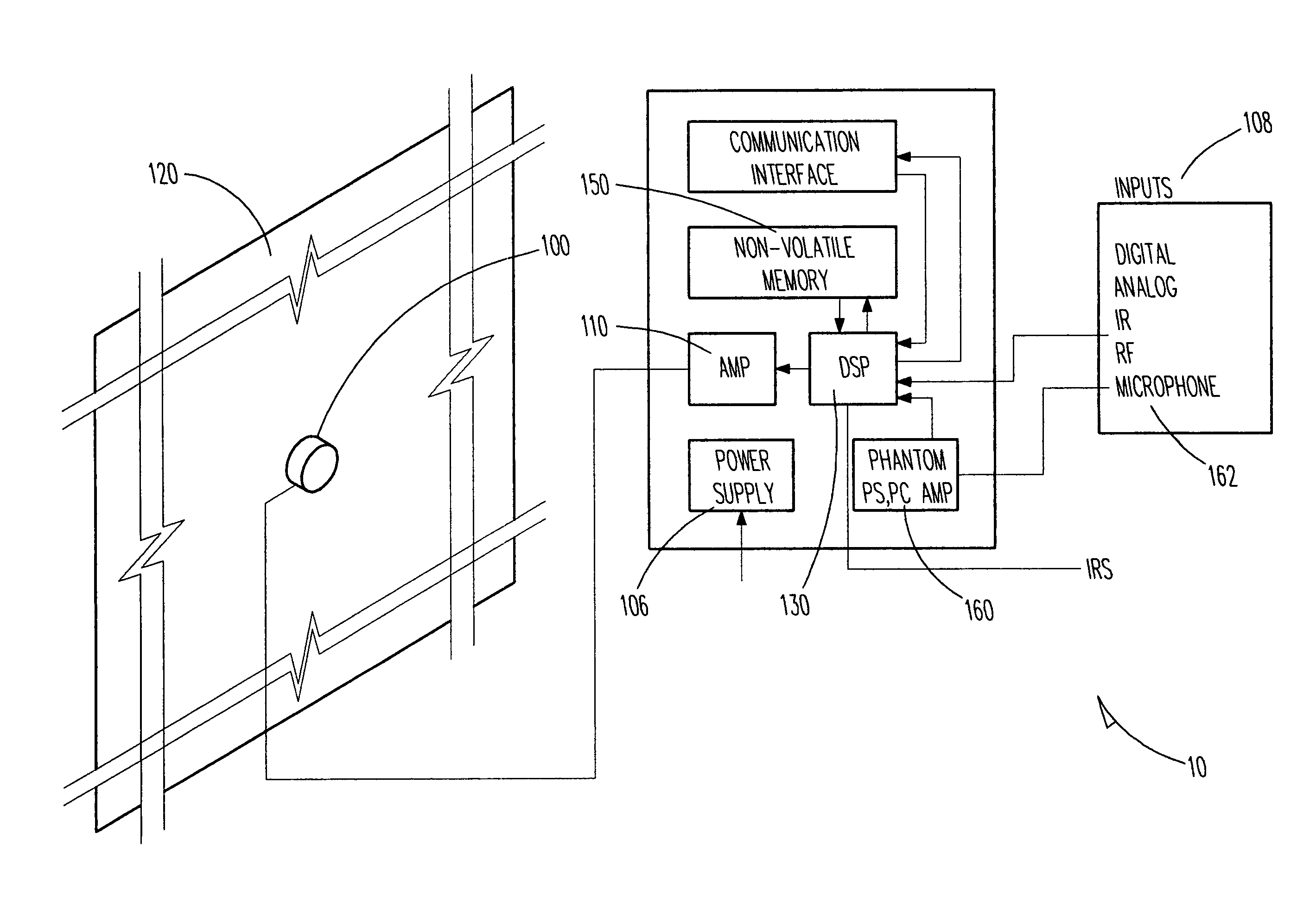
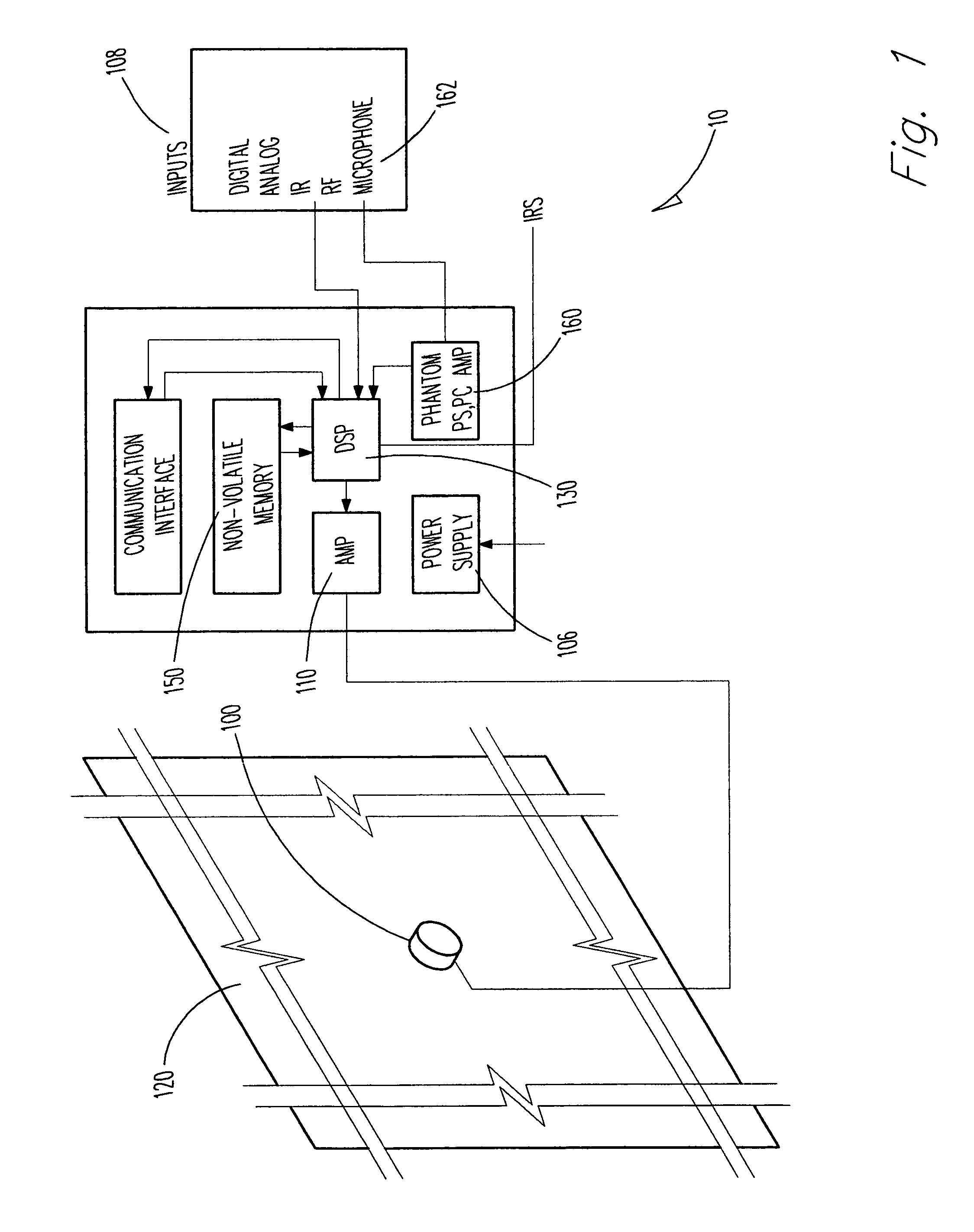
[0059]Referring first to FIG. 1 the acoustic system 10 is generally described as an acoustical soundboard panel or body 120 and an acoustic momentum type transducer 100. In the preferred embodiment, said transducer 100 is in acoustic association with said soundboard 120. A power amplifier 110, and means for processing a sound signal 130, at least one input acoustic signal 408 and a power supply 106 complete the basic system 10. In the preferred embodiment, means to process is a Digital Signal Processor. The system 10 may include an active acoustic source 12 such as background music or masking noise. The acoustical soundboard 120 comprises a traditionally non acoustic body or geometric definition and is typically comprised of, but not limited to, gypsum wallboard, wood sheet goods, fiber reinforced composites, structural panels comprising of skins and core, consolidated organic fiber, paper, steel, aluminum, glass, wood, consolidated mineral fibers, plastic and other materials where ...


PUM


Abstract

The invention converts non audio systems into distributed audio sources for active noise control solutions. The system transforms non acoustic structures into soundboards using inertial type acoustic transducers. Acoustic parameters unique for each application due to the variation in properties of the sound board are compensated by equalizers. The invention also uses damping means to limit the reflection of bending waves from the edges. The inertial type acoustic transducer is driven by an amplifier. The acoustic signal to the amplifier is modified by a signal conditioner to compensate for the non optimal response of the acoustic system. An external controller communicates with the amplifier to control its operating parameters. A series of distributed audio sources in a variety of positions may each be addressable as a node on a network wherein noise detected at that source is analyzed and the system generates sound at that source to mask the noise.

Description

FIELD OF INVENTION[0001]This invention relates to an audio system. In one aspect, this invention relates to the conversion of otherwise non audio systems such as office furniture, walls, ceilings and floors into distributed audio sources for active noise control solutions for acoustical privacy.BACKGROUND OF THE INVENTION[0002]The office workspace has undergone significant changes in the last 30 years where work areas have become smaller with increasing emphasis on collaboration.[0003]Sound control is a vital aspect of worker efficiency. Significant effort is expended in the design of the workspace in order to control the acoustics, reducing the environmental noise that interferes with a worker's concentration. In addition, public spaces are often plagued with environmental noise. It is desirable to reduce the perception and effect of environmental noise in public areas such as airports, subways, and trains.[0004]Historically, sound control has been through the deployment of passive...

Claims


Application Information

Patent Timeline
Patent Type & Authority Patents(United States)
IPC IPC(8): H04R3/02
CPCG10K2210/12G10K11/178H04R1/028H04R27/00H04K3/45H04K3/825H04K2203/12
Inventor VINCENT, STEPHEN SAINTKATZ, ROBERT
Owner KATZ ROBERT
Why Eureka
Try Eureka