Contact carrier

a contact carrier and carrier technology, applied in the direction of coupling device connection, coupling contact member, securing/insulating coupling, etc., can solve the problems of only possible fault-free contact, not always guaranteed, and minimum accuracy is necessary, so as to minimize the risk of contact carriers resting one on top of the other, and eliminate or at least minimize disadvantages

Active Publication Date: 2018-05-08
HARTING ELECTRIC GMBH & CO KG
View PDF32 Cites 0 Cited by
  • Summary
  • Abstract
  • Description
  • Claims
  • Application Information

AI Technical Summary

Benefits of technology

[0017]The problem addressed by the invention lies in presenting a contact carrier for plug connectors which eliminates or at least minimizes the disadvantages of the contact carriers and plug connectors known from the prior art. Here, the contact carrier and the contact carrier of a second plug connector can be easily guided together one inside the other. The risk of the contact carriers resting one on top of the other will be minimized, even in the event of inaccurate contacting.
[0024]Between the side faces and the cover face, the contact carrier forms a peripheral edge. In accordance with the invention the edge is provided with a chamfer serving as an insertion bevel. The insertion bevel solves the problem addressed by the invention of increasing the plugging reliability and preventing faulty plugging caused by contact carriers resting one on top of the other.
[0026]The design of the insertion bevel at a 45° angle has proven to be particularly expedient. However, insertion bevels having angles between 20° and 70° are also conceivable. Insertion bevels in the range between 35° and 55° are advantageous.
[0031]The stepped recess is expediently formed with the same dimensions as the insertion bevel on the contact carrier. It is thus ensured that a resting in the rounded corner region is prevented, even with maximum offset of two contact carriers relative to one another.

Problems solved by technology

A disadvantage in the case of these modular and non-modular insulation bodies for plug connectors known from the prior art is that, when the plug connector is contacted with a mating plug connector, a minimum level of accuracy is necessary.
Fault-free contacting is only possible when enough importance is placed on the alignment of the plug connector and mating plug connector.
However, this is not always ensured when the contacting of plug connectors is not performed manually, i.e. by hand by a user, but is performed automatically.
If this is not the case, this may lead in the worst-case scenario to the destruction of the plug connector when the insulation bodies do not slide correctly inside one another and instead rest on top of one another.
An error of this type in a large installation can only be rectified with difficulty.
In the worst-case scenario, a contacting of a plurality of modular plug connectors is not even possible without human intervention.
Faulty plugging of this type occurs particularly when the tolerances of rectangular or square contact carriers in two spatial dimensions are used to the maximum.
Faulty plugging of the contact carrier is the result.

Method used


Image

  • Contact carrier
  • Contact carrier
  • Contact carrier

Examples


Embodiment Construction

[0040]The figures contain schematic illustrations simplified in part. Identical reference signs are sometimes used for elements that are similar, but possibly not identical. Different views of the same elements could be scaled differently.

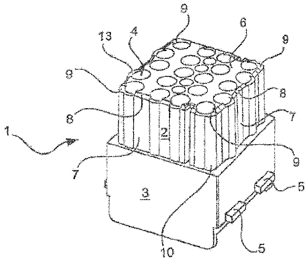
[0041]FIG. 1 shows a contact carrier 1 from a perspective view. The contact carrier 1 has two regions, wherein the region illustrated here at the bottom forms a retaining region 3 and the region illustrated here at the top forms a plugging region 2.

[0042]A multiplicity of cavities 4 are formed in the contact carrier 1. Here, the cavities 4 extend from a cover face 6 terminating the plugging region 2 through the entire plugging region 2 and the entire retaining region 3. The cavities 4 exit from the retaining region 3 of the contact carrier 1—and also from the plugging region 2—on the terminating face of the retaining region 3 (said face not being visible here).

[0043]The cavities 4 are intended to receive contact elements. Here, contact elements are...


PUM


Abstract

The invention relates to a contact carrier (1) for holding contact elements and for bringing into contact with a corresponding contact carrier. The contact carrier (1), which is made of an insulating material, has a plurality of cavities (4) in order to hold the contact elements, which cavities extend in a plugging direction through the entire contact carrier (1) and a retaining region (3) of the contact carrier and a plugging region (2) of the contact carrier. According to the invention, the contact carrier (1) has an insertion bevel (8), which insertion bevel makes it easier to bring the contact carrier (1) into contact with a corresponding contact carrier. The invention relates to improvements in the plugging region in order to avoid incorrect plugging of two contact carriers, in particular a resting of the contact carriers during the plugging process.

Description

CROSS REFERENCE TO RELATED APPLICATIONS[0001]Not applicable.STATEMENT REGARDING FEDERALLY SPONSORED RESEARCH OR DEVELOPMENT[0002]Not applicable.BACKGROUND OF THE INVENTION[0003]The invention relates to a contact carriers.[0004]Contact carriers are required in connection technology in order to receive contacts, preferably in plug connectors. Here, the contact carrier serves to receive contact elements such as electric, pneumatic or optical contacts.[0005]The contact carrier has cavities, in which the contact elements are received and secured. The cavities are usually formed here as bores, which penetrate the contact carrier completely. On a side of the contact carrier referred to as the connection side, a conductor can thus be conductively connected to the contact element received in the cavity.[0006]On the side opposite the connection side, referred to as the plugging side, the contact element received in the cavity is provided with a second contact carrier for contacting. The secon...

Claims


Application Information

Patent Timeline
Patent Type & Authority Patents(United States)
IPC IPC(8): H01R13/60H01R13/631H01R13/514H01R13/502H01R13/518
CPCH01R13/514H01R13/6315H01R13/518H01R13/502H01R13/40
Inventor MEIER, HEIKOSCHNIEDER, STEFAN
Owner HARTING ELECTRIC GMBH & CO KG
Why Eureka
Try Eureka