

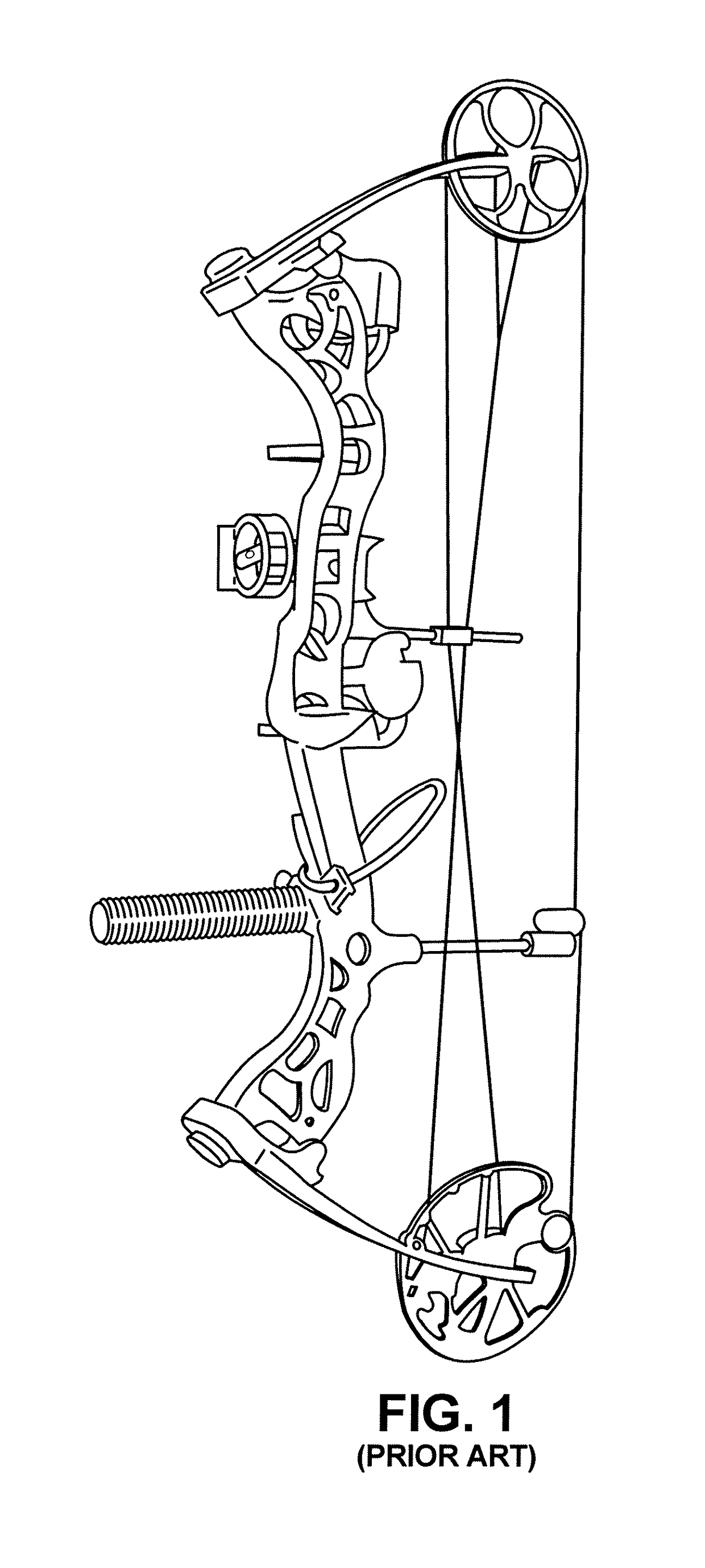
Archery bow overdraw sensing and light indicator system
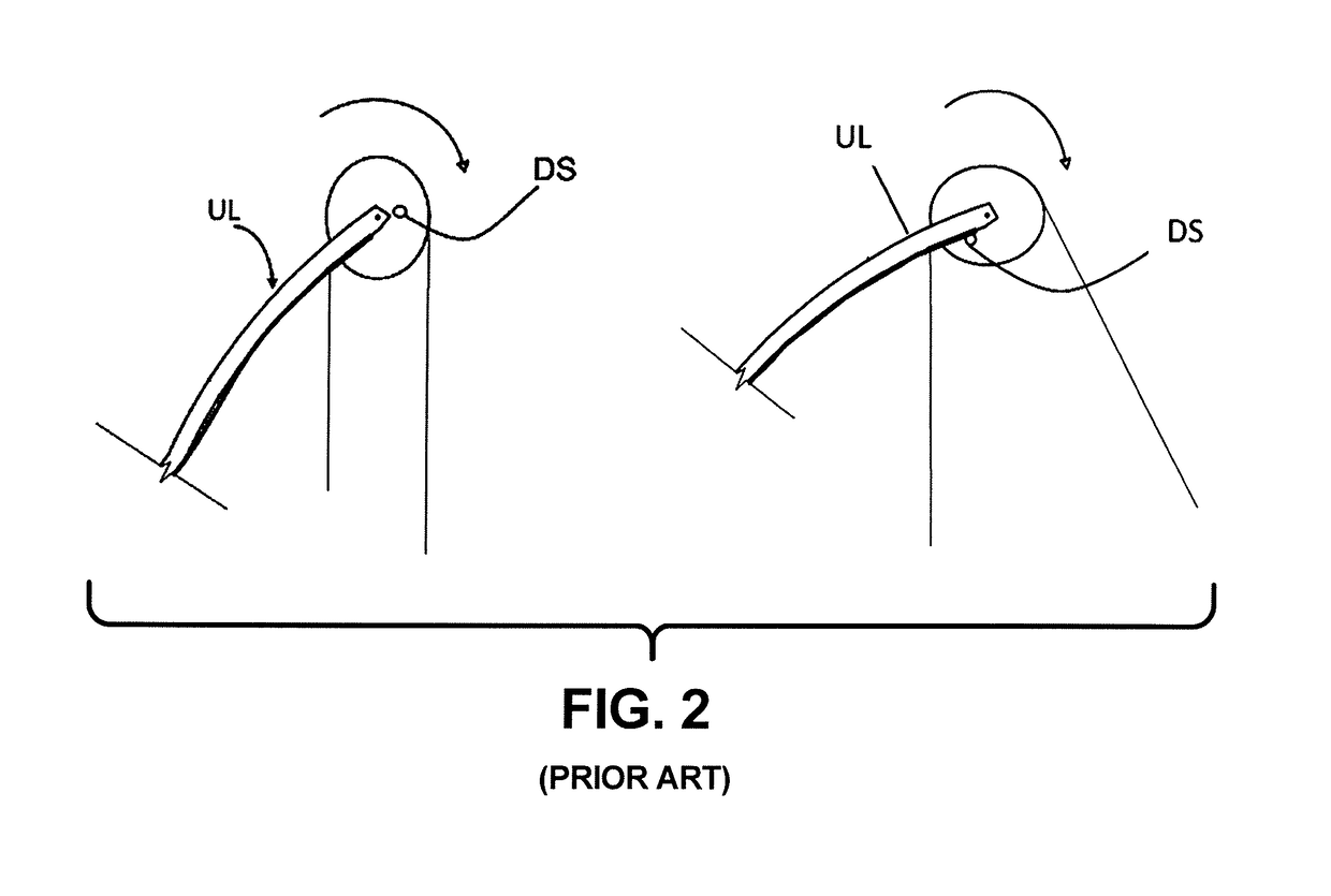
an archery bow and sensing technology, applied in the field of force sensors, can solve the problems of under or overdrawing of the bow, the archer cannot feel the force he is pulling on the bow string or into the bow, and the draw stop is not as effective as an indicator of proper tension
- Summary
- Abstract
- Description
- Claims
- Application Information
AI Technical Summary
Benefits of technology
Problems solved by technology
Method used
Image

Examples
Embodiment Construction
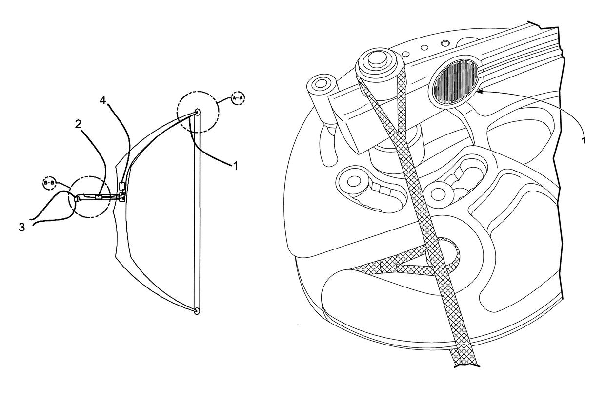
[0029]In the Figures is shown an archery pressure apparatus. In particular, FIGS. 3A-C show the parts describes below, where each part labeled with a reference numeral corresponding to the part number below.
Definition of Parts:
1. FSR
[0030]A force-sensitive resistor (alternatively called a force-sensing resistor or simply an FSR) 1 has a variable resistance as a function of applied pressure. In this sense, the term “force-sensitive” is misleading—a more appropriate term would be “pressure-sensitive,” since the sensor's 1 output is dependent on the area on the sensor's 1 surface to which force is applied.
[0031]Force sensing resistor 1 (see FIG. 4) for this invention maybe a 0.5 inch diameter, 1 oz, 22 pound flexible resister 1 made by Pololu, Part Number 1696, UNSPSC Code 32121600 (the invention is not necessarily limited thereby). The invention can use other types of sensors such as strain gauges; load cells that use transducers to convert into measurable electrical outputs or hydrau...
PUM
 Abstract
Description
Claims
Application Information