Removable end cap assembly for a level

a technology of end caps and components, applied in the field of tools, to achieve the effect of reducing weight, limiting energy transfer to other components, and saving materials usage and cos

Active Publication Date: 2018-05-15
JOHNSON LEVEL & TOOL MFG
View PDF28 Cites 4 Cited by
  • Summary
  • Abstract
  • Description
  • Claims
  • Application Information

AI Technical Summary

Benefits of technology

[0005]It is therefore an object of the present invention to provide an end cap for a level that can be fastened to and removed from the frame by a user simply and quickly and without the use of additional materials and special tools, and without removing any pieces and parts from the level or the end cap.
[0009]The end cap includes a main cap body and the sliding retainer. The main cap body may be constructed of any single material or combination of rugged materials, such as a rubber or plastic capable of absorbing impacts and limiting energy transfer to other components. Furthermore, the main cap body may be constructed as a single part or an assembly of sub-parts, and may be fully or partially hollow to conserve materials usage and cost, reduce weight, or to provide functional interior surfaces that cooperate with other structure, such as the sliding retainer.

Problems solved by technology

One drawback of level end caps is that they prevent the level gauging surface from reaching all the way to a wall that defines a corner, which is disadvantageous when it is desired to use the gauging surface to draw a line all the way into the corner.

Method used


Image

  • Removable end cap assembly for a level
  • Removable end cap assembly for a level
  • Removable end cap assembly for a level

Examples


first embodiment

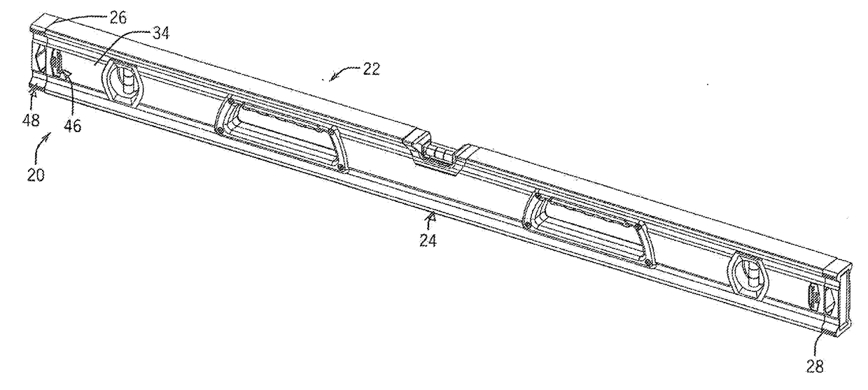
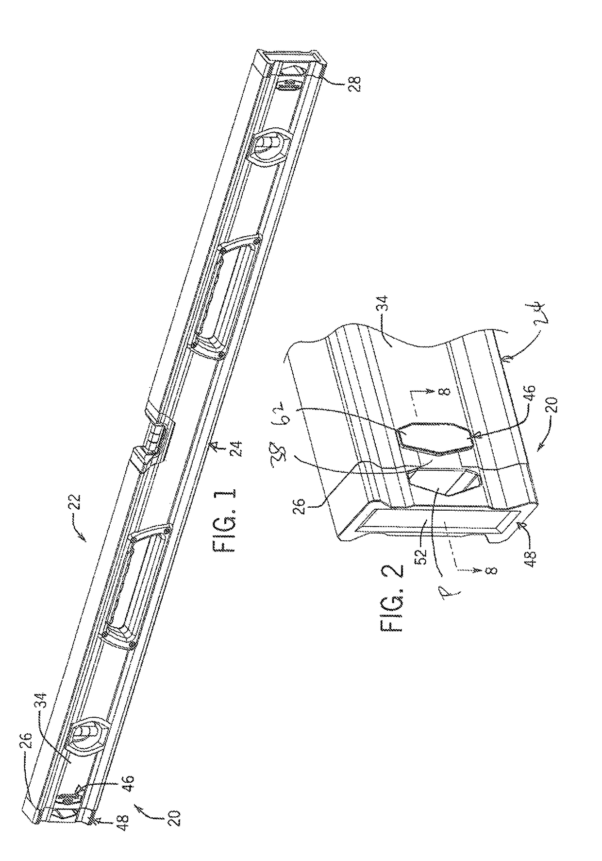
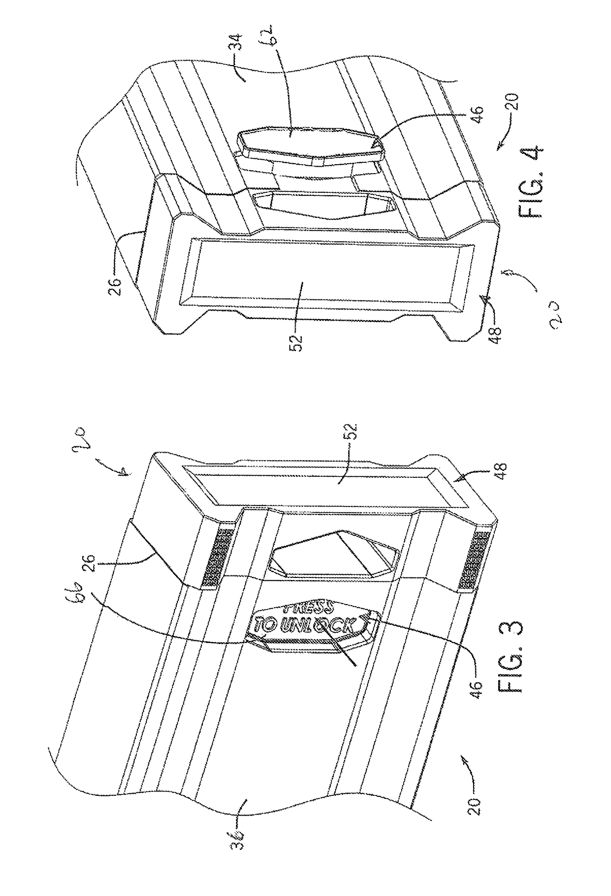
[0037]With reference to the drawing figures in which like reference numerals designate like parts throughout the disclosure, a representative first embodiment of the present invention is illustrated in FIGS. 1-10 in the form of a removable end cap assembly shown generally at 20 coupled with a level 22, which includes an elongate box beam-type frame 24 with a closed polygonal cross section and a first end 26 and a second end 28, either of which end may be provided a removable end cap 20 accordance with the present invention. Level 22 may include one removable end cap 20 in cooperation with each end 26, 28, or alternatively with only one of the ends of the frame 24.

[0038]When viewed along the elongate axis with end cap 20 removed, it can be seen that frame 24 includes a first end edge 30 and an opposing second end edge 32 at first end 26, which correspond to a first side wall 34 and an opposing second side wall 36, respectively. First and second side walls 34, 36 extend between and in...

second embodiment

[0046]FIGS. 11-22 illustrate the present invention, in the form of a removable end cap arrangement for an I-beam type level. As shown in FIGS. 11-16, a level 72 includes an elongate frame 74 with an open I-beam cross section, including a web 76 spanning between an upper flange 78 and a lower flange 80. Level 72 includes an end cap 82 with a main cap body 84 and a sliding retainer 86. In the illustrated embodiment, web 76 is oriented perpendicular to flanges 78, 80, although it is understood that web 76 may be oriented at any other desired angle. When viewed along the elongate axis with end cap 82 removed, an edge 88 corresponding to an end 96 of frame 74 is revealed. Each of web 76 and flanges 78, 80 have thicknesses that may vary.

[0047]As illustrated in FIGS. 15-17, an opening or recess 94 extends normally through web 76 and edge 88, opening onto frame end 96. Recess 94 includes a pair of channels 98, each of which has an undercut configuration that defines engagement structure in ...


PUM


Abstract

An end cap arrangement for a level, in which a frame of the level includes and end defining a recess and one or more engagement protrusions. The end cap arrangement includes an end cap body and a retainer that is movable between engaged and release positions. The retainer includes retainer structure that engages the engagement protrusions when the retainer is in the engaged position to prevent removal of the end cap body. The retainer also includes clearance structure that can be moved past the engagement protrusions to enable the end cap body to be removed from the level frame. The end cap arrangement may be used with either a box beam or I-beam level frame.

Description

CROSS REFERENCE TO RELATED APPLICATION[0001]This application claims priority from U.S. Provisional Patent Application No. 62 / 045,230, filed Sep. 3, 2014, the subject matter of which is incorporated by reference in its entirety.BACKGROUND AND SUMMARY[0002]This invention relates to a tool such as a level, and more particularly to a removable end cap feature for a level.[0003]A level generally includes at least one bubble vial secured to an elongate frame. The frame may be constructed of metal, plastic, organic material (e.g., wood), or other rigid material, and has a cross section that may vary between and within models, but commonly is in the form of either a box beam having a generally rectangular cross-section or an I-beam having an I-shaped cross-section. Alternatively, the frame may have other forms suitable for specific applications (e.g., an angular frame for leveling pictures or posts). The bubble vial indicates the orientation of the level, e.g., relative to a horizontal, ver...

Claims


Application Information

Patent Timeline
Patent Type & Authority Patents(United States)
IPC IPC(8): G01C9/02
CPCG01C9/02
Inventor WOJCIECHOWSKI, TIMOTHY J.
Owner JOHNSON LEVEL & TOOL MFG
Why Eureka
Try Eureka