

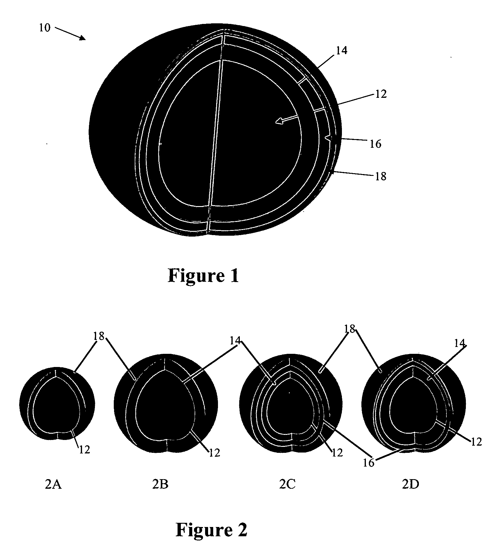
Layered nanoparticles with controlled energy transfer between dopants
a technology of energy transfer and nanoparticles, which is applied in the direction of cellulosic plastic layered products, natural mineral layered products, transportation and packaging, etc., can solve the problems of undesirable energy transfer, low energy transfer efficiency, and low economic benefits of early attempts at forming spectrally engineered emissive materials, etc., to achieve large energy transfer between the optically active ions and control the effect of energy transfer
- Summary
- Abstract
- Description
- Claims
- Application Information
AI Technical Summary
Benefits of technology
Problems solved by technology
Method used
Image

Examples
example
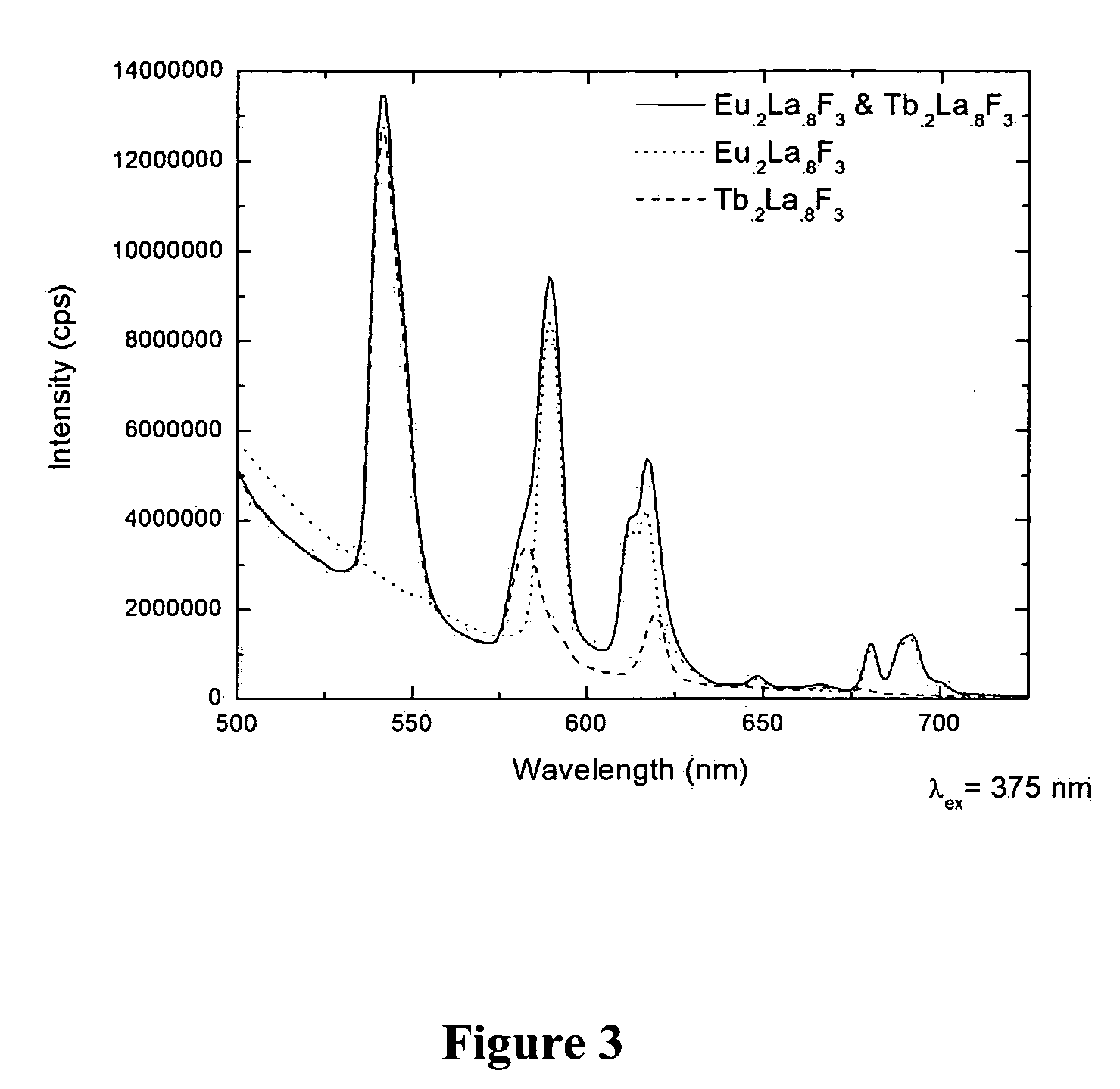
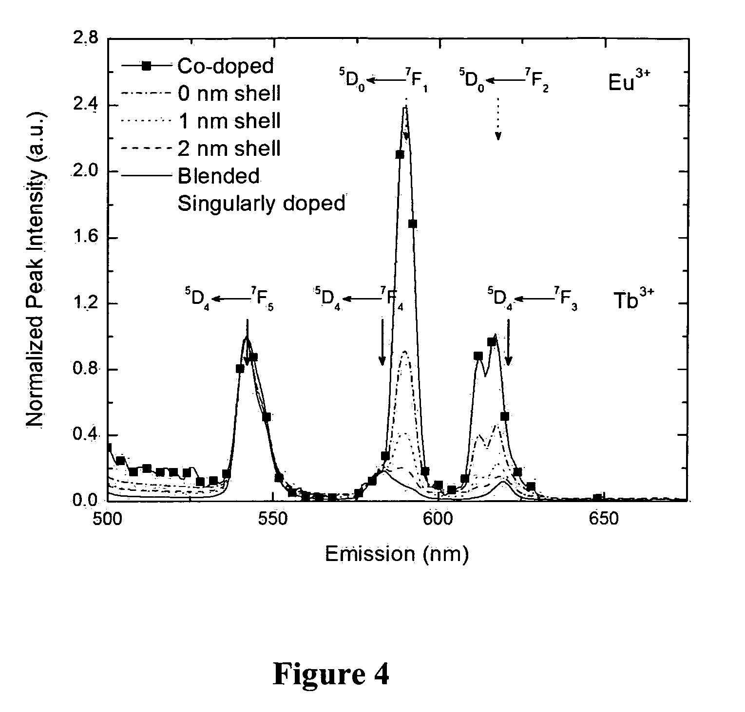
[0062] Synthesis: A solution of 614 milligrams (mg) of ammonium di-n-octadecyldithiophosphate (ADDP) and 126 mg of NH4F in 70 milliliter (mL) ethanol / water was heated to 75° C. A 2 mL aqueous solution with total molar Ln(NO3)3 concentration of 1.33 millimole (mmol) was then added drop-wise to the stirring fluoride solution to form the core of the particles. After stirring for 10 minutes, the first shell was grown by the alternating addition in 10 parts of a 2 mL aqueous NH4F (126 mg) solution and a 2 mL aqueous Ln(NO3)3 solution with total molar concentration of 1.33 mmol. The composition of the Ln(NO3)3 solution will be the composition of the shell. In this work, Eu(NO3)3 and / or Tb(NO3)3 were used as dopants at 20 mol % concentrations (i.e., Eu.2La.8F3 and Tb.2La.8F). The process was repeated for each shell with variation in reactants as to content and / or presence of dopant. After the formation of the last shell, the solution was stirred for an additional 2 hours and cooled to room...
PUM
| Property | Measurement | Unit |
|---|---|---|
| thickness | aaaaa | aaaaa |
| thickness | aaaaa | aaaaa |
| thickness | aaaaa | aaaaa |
Abstract
Description
Claims
Application Information