Determining minimum energy pulse characteristics in an ink jet print head

A print head, pulse technology, applied in the direction of printing device, printing, inking device, etc., can solve the problem of chip overheating and so on

Inactive Publication Date: 2005-06-08
LEXMARK INT INC
View PDF1 Cites 0 Cited by
  • Summary
  • Abstract
  • Description
  • Claims
  • Application Information

AI Technical Summary

Problems solved by technology

This causes undesired chip overheating

Method used


Image

  • Determining minimum energy pulse characteristics in an ink jet print head
  • Determining minimum energy pulse characteristics in an ink jet print head
  • Determining minimum energy pulse characteristics in an ink jet print head

Examples


Embodiment Construction

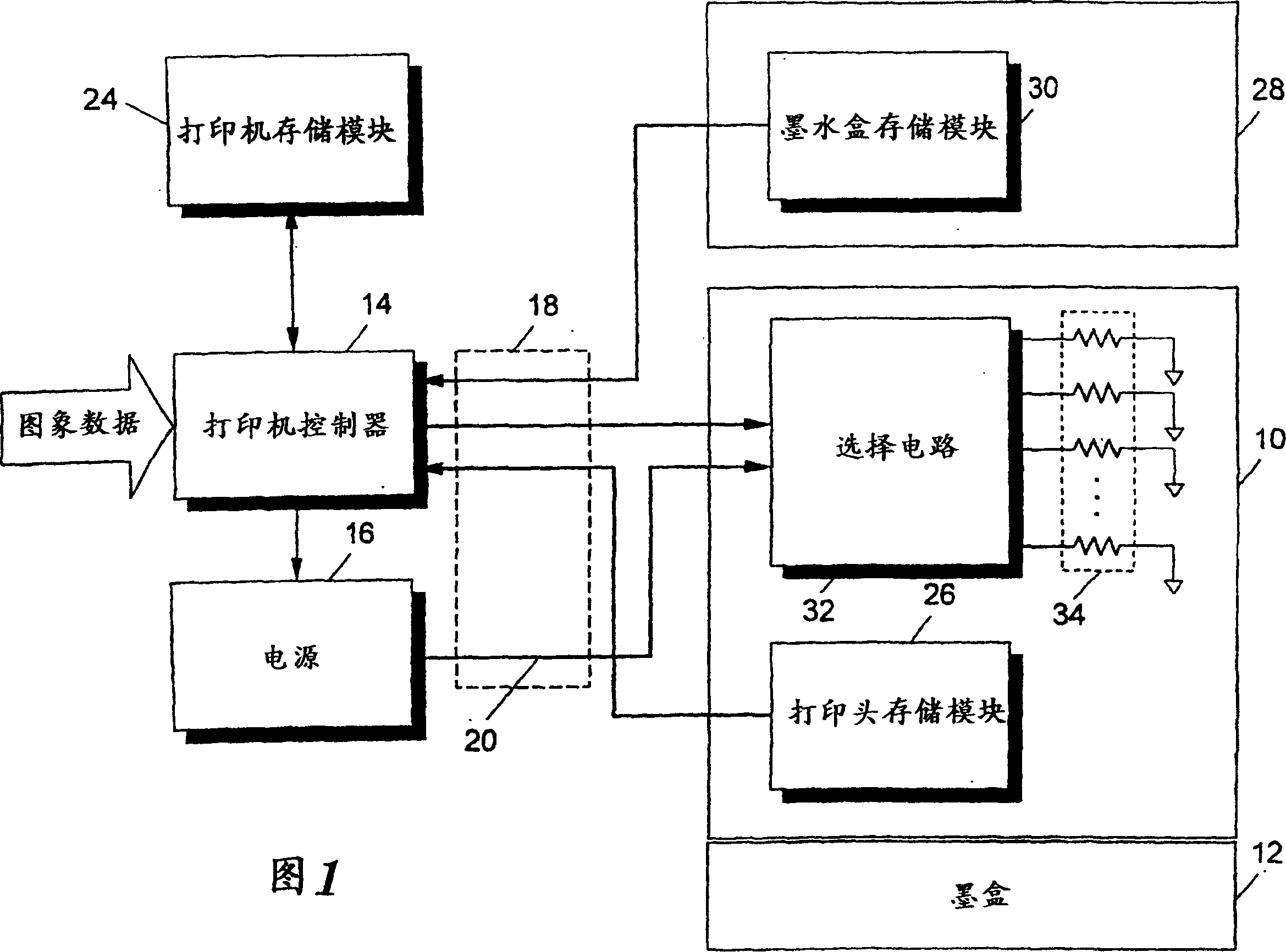
[0019] Fig. 1 shows a functional block diagram of a preferred embodiment of an ink jet printer according to the present invention. Preferably, the printer includes a replaceable printhead 10 mounted on a carriage 12 which allows the printhead to translate across the print medium. When installed in a printer, the printhead 10 is electrically connected to a printer controller 14 and a power supply 16 . Since the controller 14 and power supply 16 are preferably placed in a fixed location in the printer rather than mounted on the carriage 12, the electrical connection between the printhead 10 and the controller 14 and power supply 16 is through a soft TAB circuit 18. .

[0020] As shown in FIG. 1, the controller 14 receives image data from a host computer, and generates control signals to control the operation of the printhead 10 based on the image data. Controller 14 also controls power supply 16 to generate a supply voltage Vs on line 20 .

[0021] As discussed in more detail...


PUM


Abstract

A system for providing an optimal pulse of energy to a resistive heating element (34) in an inkjet printhead (10). The optimum energy pulse provides an optimum energy density at the surface of the heating element (34) to achieve optimum buildup of ink located adjacent to the surface of the heating element (34). The system includes storing in a memory (26) values ​​related to heating element dimensions, heating element electrical characteristics and ink characteristics. Also stored in memory are expressions for providing arithmetic relationships between heating element dimensional values, heating element electrical values, ink properties and the magnitude and duration of the optimum energy pulse. The system also includes retrieving stored values ​​and expressions from memory and determining an optimum energy pulse magnitude and duration based on the expressions. The system also generates and provides optimal energy pulses to the heating element (34) based on the determined amplitude and duration. The energy density provided by the optimal energy pulse is high enough to form a bubble and a small drop of ink near the heating element, but not high enough to be wasted after the bubble is formed and cannot be delivered to the ink.

Description

[0001] The present invention is a divisional application of Chinese patent application 01815429.8, titled "Determining the Minimum Energy Pulse Characteristics in an Inkjet Printhead". technical field [0002] The present invention is generally directed to inkjet printing devices and printheads. More specifically, the present invention is directed to a method for determining optimum characteristics of energy pulses provided to resistive heating elements in an inkjet printhead, and for determining optimum characteristics of resistive heating elements. Background technique [0003] A thermal inkjet printer forms an image on a print medium by expelling small ink droplets from an array of nozzles in an inkjet printhead as the printhead sweeps across the print medium. When a current pulse is passed through a resistive heating element, the heat generated causes ink in contact with the heating element to coalesce to form ink drops. Typically each nozzle of the array has a correspo...

Claims


Application Information

Patent Timeline
Patent Type & Authority Applications(China)
IPC IPC(8): B41J2/05B41J2/14
CPCB41J2/04553B41J2/04563B41J2/0458B41J2/0459B41J2/04591B41J2/04593B41J2/14129B41J2202/17B41J2/04541B41J2/14427B41J29/393
Inventor 罗伯特·W.·科奈尔
Owner LEXMARK INT INC
Why Eureka
Try Eureka