Wind power generator

Inactive Publication Date: 2017-01-05
ABB (SCHWEIZ) AG
View PDF3 Cites 1 Cited by
  • Summary
  • Abstract
  • Description
  • Claims
  • Application Information

AI Technical Summary

Benefits of technology

[0009]The advantage of the rotor structure is that the energy transfer between the rotor and the stator is considerably better than in the previously known structures. This leads to better efficiency of the structure. Further, as the magnetic poles are placed in the surface of the rotor rim in a conventional manner, the stator structure can be conventional and no re-design is needed. A further advantage of the wind power generator of the invention is that the rotor poles can be structured more freely allowing produce output voltage from the stator having low content of harmonics. Further, the problematic cogging torque phenomena can be alleviated with the rotor pole design.
[0010]The superconducting coil and the co

Problems solved by technology

The short magnetic coupling further means that energy transfer between the stator and the rotor is not optimal.
The fixing of the superconductor coil and the application of required cryo enginee

Method used


Image

  • Wind power generator
  • Wind power generator
  • Wind power generator

Examples


Embodiment Construction

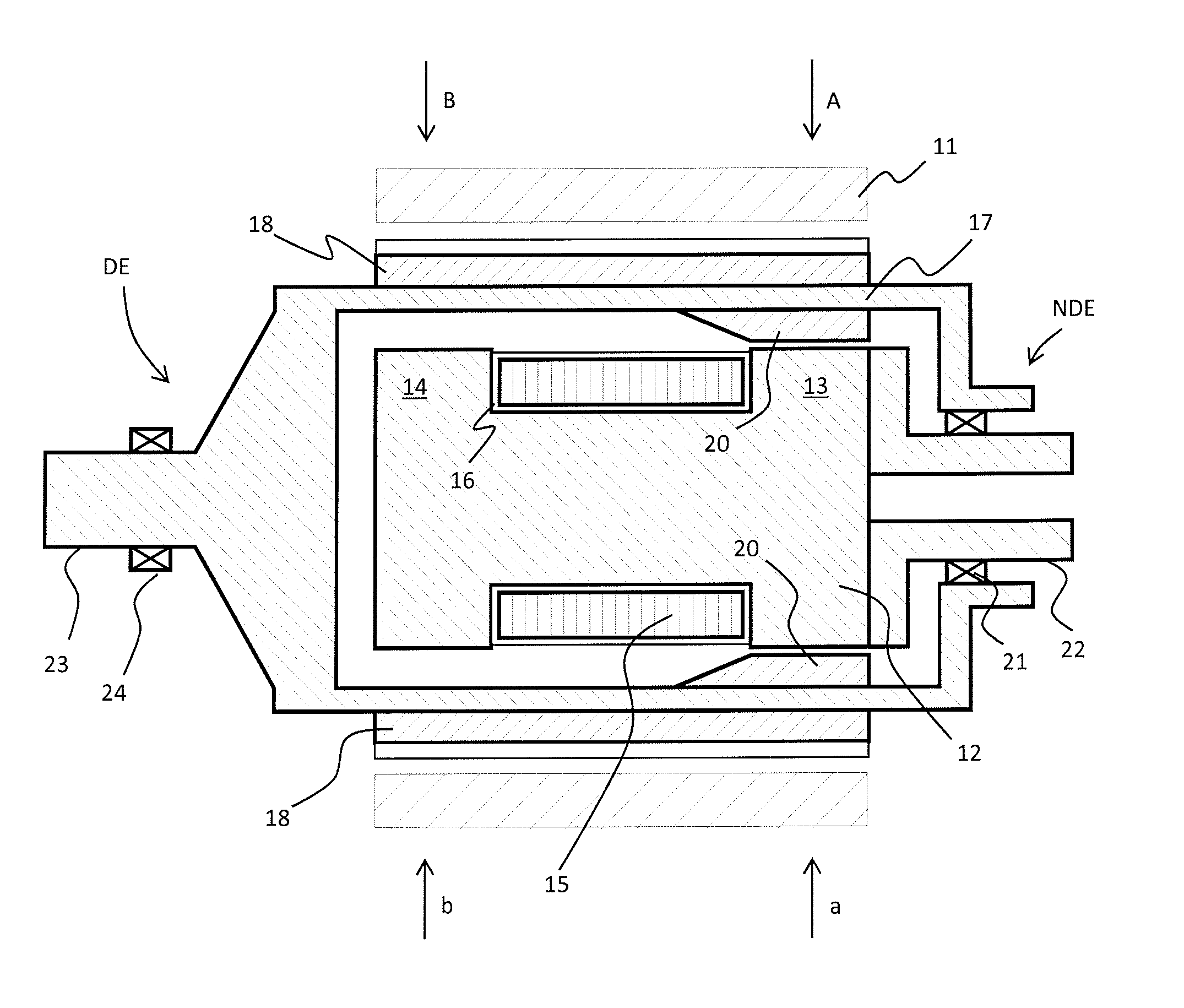
[0017]FIG. 1 shows a cross section of the wind power generator of an embodiment of the invention. The generator is cut in half in longitudinal direction that is the direction of the shaft of the generator. FIG. 1 shows the stator 11 of the generator being the outmost part of the generator. The stator is equipped with stator windings. The stator windings of the generator of the present disclosure can be windings of any known kind. Typically the stator windings are a multi-phase windings, preferably three-phase windings. As the rotor structure of the wind power generator of the invention forms magnetic poles which are comparable to permanently magnetized poles, the stator windings can be of design commonly used in connection with synchronous generators. More specifically, the stator windings are formed in the stator core such that the axial length of the stator winding corresponds to the length of the stator core. The stator windings thus extend in the axial direction of the core for ...


PUM


Abstract

Wind power generator (WPG) comprising a stator, rotor with a shaft connectable to wind turbine and a stationary superconducting coil for magnetizing the wind power generator rotor, the WPG stator comprising a multi-phase winding for producing electricity. The WPG is a synchronous generator, and the superconducting coil comprises end portions arranged to be magnetized with opposing polarities by a superconducting coil, the rotor comprises poles extending in the surface of the rotor in the direction of the shaft of the generator, the poles arranged to be magnetized using the superconducting coil, each rotor pole extends inwardly at one end of the pole such that the inwardly extended end is arranged in the vicinity of an end portion of the superconducting coil for magnetizing the rotor pole and the rotor poles comprises pole shoes formed to provide sinusoidally varying air gap flux in the air gap between stator and rotor.

Description

FIELD OF THE INVENTION[0001]The present invention relates to wind power generators, and more particularly wind power generators employing superconductors for providing rotor magnetization.BACKGROUND OF THE INVENTION[0002]It is known in the art of rotating electrical machines to use super-conducting wires for producing excitation to the rotating machine.[0003]One example of a structure employing a superconducting coil for magnetizing the rotor is presented in JP55005043 A. In this document a superconducting coil surrounds an induction core that forms the rotor structure. When a DC current is fed to the coil, the induction core is magnetized such that salient poles are formed at both ends of the inductor core. The stator of the machine comprises corresponding poles at both ends of the inner structure of the stator. The stator ends are energized with alternating current for obtaining a force driving the machine. Alternatively, when the rotor is rotated by an external force, generated v...

Claims


Application Information

Patent Timeline
IPC IPC(8): H02K7/18H02K1/24H02K7/08H02K55/02F03D9/00F03D9/25H02K19/16H02K1/12
CPCH02K19/24H02K55/02H02K1/24H02K7/1838Y02E10/72Y02E40/60F03D9/25H02K1/12H02K7/085H02K7/183H02K19/16
Inventor SILANDER, EINO
Owner ABB (SCHWEIZ) AG
Why Eureka
Try Eureka