Transfer assembly

a technology of transceivers and parts, applied in the field of transceivers, can solve the problems of electromagnetic coupling, restricted patient's freedom of movement, and common source of infection of lead-through devices in the skin

Active Publication Date: 2016-08-30
DEUTSCHES ZENTRUM FUER LUFT & RAUMFAHRT EV
View PDF11 Cites 9 Cited by
  • Summary
  • Abstract
  • Description
  • Claims
  • Application Information

AI Technical Summary

Benefits of technology

[0011]It is an object of the present invention to provide a simple transfer assembly which allows for an improved check of the alignment of the transfer coil of the implant with the transfer coil of the supply means.
[0015]The locating signal can be issued acoustically, optically or in any other way, and enables the patient to correct the position of the transfer coil of the supply means such that the transfer coil of the supply means is to a large extent congruent with the transfer coil of the implant. Since it is possible to check the offset of the transfer coil of the implant relative to the transfer coil of the supply means, the offset can be continuously checked and kept at a low level. Thus the efficiency and / or the performance of the transfer, in particular the energy transfer between the supply means and the implant, are improved. This, in turn, reduces the heat development, improves the service life of the components involved, and, in the case of data transfer, improves the quality of the data transfer.
[0018]Preferably, a transmitting element of the transmitter is configured as a coil, and the receiver comprises a magnetic field receiving element. The receiving element may also be configured as a coil or as a Hall sensor. The transmitting element may be the transfer coil of the implant, but may also be a separate transmitting element coil. The transmitting element or elements are connected with the receiving element or elements via an electromagnetic field. The intensity of the field detected by the receiving element or elements is a measure of the distance of the receiving element configured as a coil. Preferably, the receiving coil has a considerably smaller circumference than the transfer coil of the supply means and / or the transfer coil of the implant. This allows the alignment of the two transfer coils relative to each other to be determined in a considerably more exact manner.
[0023]For preventing disturbances by external light sources, the optical signals may be modulated, they may be pulsed for example. Its pulsating frequency allows the optical transmitting element to be clearly identified on the receiver side and to be differentiated from the light coming from other light sources. If the transmitting element of the device involved also acts as a transmitting element for the optical data transfer between the implant and the supply means, the offset recognition is not activated continuously but in a clocked manner, for example.

Problems solved by technology

The line lead-through devices in the skin are a common source of infection.
Further, the patient is restricted in his freedom of movement by the line lead-through devices.
However, since the transfer coil of the supply means is not fixed to the skin by gluing, there is the risk that, during the inductive transfer, the belt and the transfer coil of the supply means shift when the patient moves, and therefore the electromagnetic coupling and thus the efficiency of the energy transfer and the data transfer are reduced.
Another problem is the exact placing and alignment of the extracorporeal transfer coil of the supply means over or on top of the intracorporeal transfer coil of the implant.
Further, a direction of offset cannot be clearly determined from the point of view of the supply means.

Method used


Image

  • Transfer assembly
  • Transfer assembly
  • Transfer assembly

Examples


first embodiment

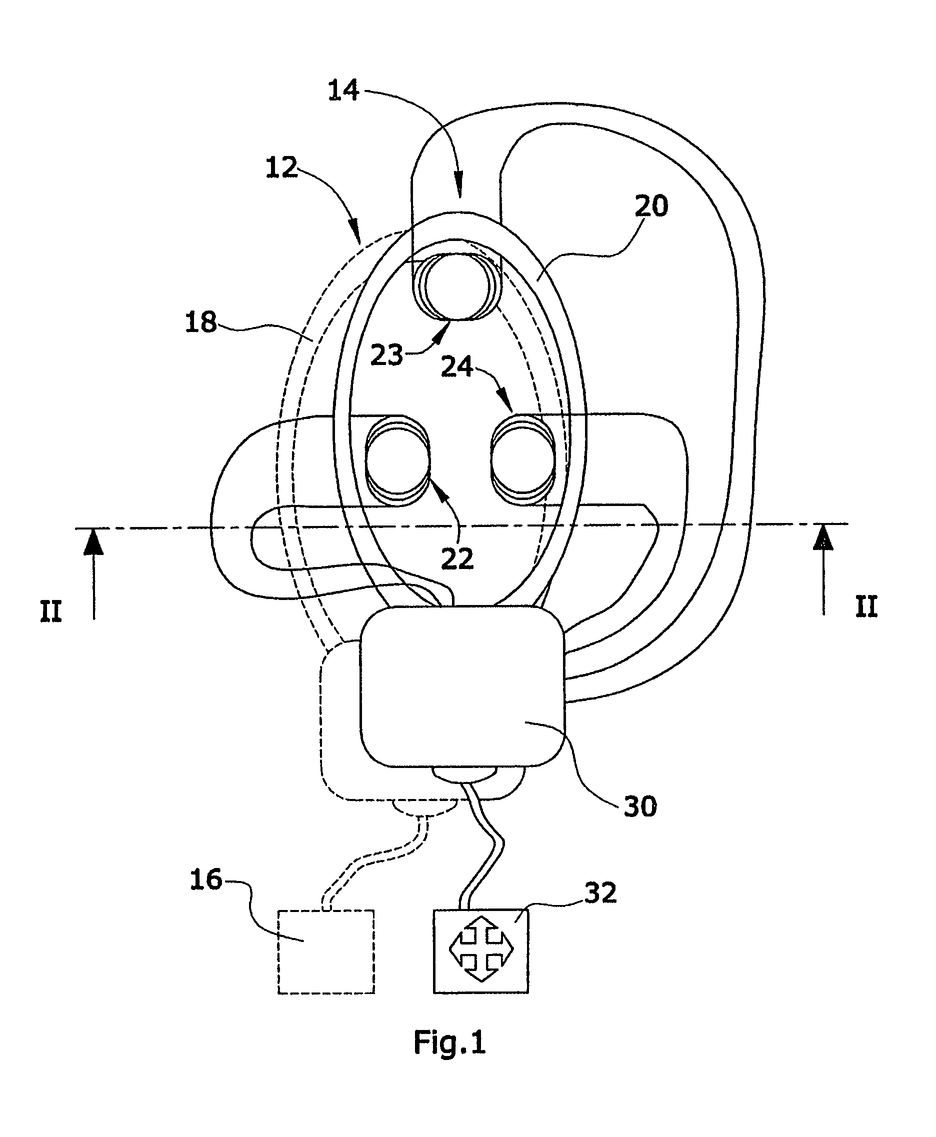
[0029]FIG. 1 shows a transfer assembly 10. The transfer assembly 10 comprises an intracorporeal implant 12 represented by a dashed line, and an extracorporeal supply means 14. The implant 12 is a blood pump for supporting a patient's heart activity, for example, and comprises a pumping means 16. The pumping means 16 usually operates continuously and has an energy requirement ranging from several watts to 20 watts. The implant 12 is a so-called fully implanted implant, i.e. the implant 12 has no physical connection with the outside of the body.

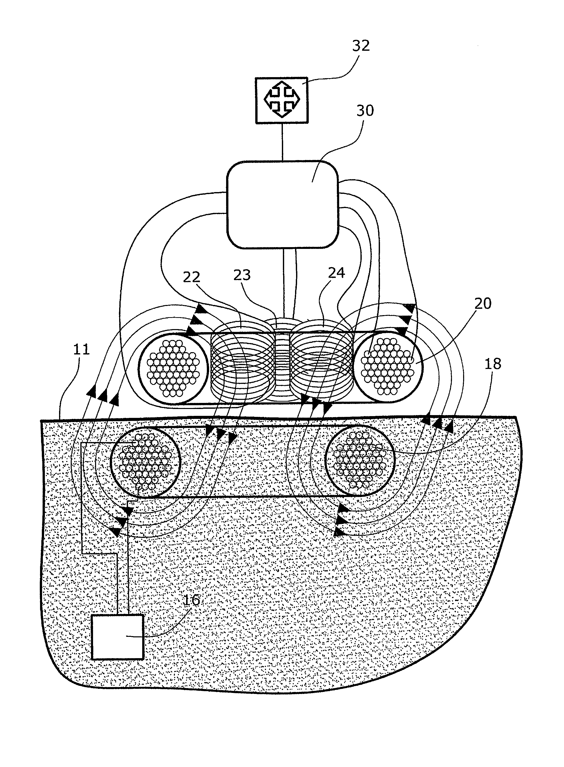
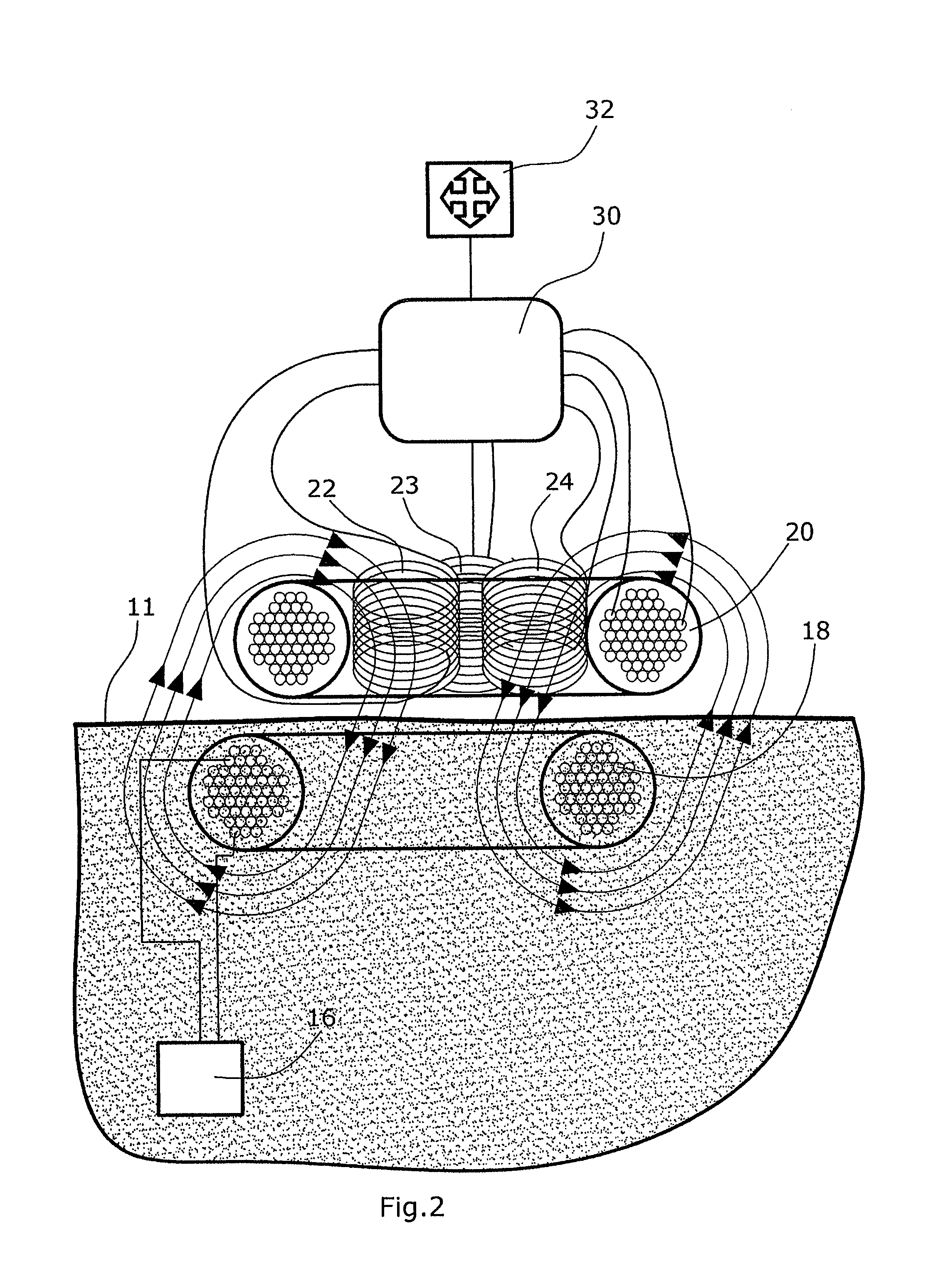
[0030]The electrical energy required for operating the blood pump 16 must therefore be transferred in a cordless manner. The transfer is performed via an implant 12 transfer coil 18 which is implanted immediately beneath the skin, and an extracorporeal transfer coil 20 of the extracorporeal supply means 14. In the transfer coil 20 of the supply means 14 small coils configured as receiving elements 22,23,24 are arranged which define inductive re...

second embodiment

[0035]FIG. 3 shows a transfer assembly 50, wherein the transmitter is defined by an optical transmitting element 52, and the receiver is defined by three optical receiving elements 54,55,56.

[0036]The transmitting element 52 is an infrared diode which is operated in a pulsed manner. The receiving elements 54,55,56 are photo diodes comprising infrared filters. In an evaluation module 30′ the signals coming from the optical receiving elements 54,55,56 are filtered by a band-pass filter whose filtering frequency is the pulse frequency at which the transmitting element 52 is chopped.

[0037]The evaluation of the infrared light intensity emitted by the transmitting element 52 and received by the receiving elements 54,55,56 enables the evaluation module 30′ to send a signal to the locating display 32, said signal furnishing information both on the direction of offset and on the amount of offset between the transfer coil 20 of the supply means 14 and the transfer coil 18 of the implant 12.

[00...


PUM


Abstract

A transfer assembly comprising an intracorporeal transfer coil of an implant, and an extracorporeal transfer coil of an extracorporeal supply unit. The transfer coil of the implant has permanently associated therewith a transmitting element. The transfer coil of the supply unit has permanently associated therewith at least one receiving element. Further, the supply unit comprises an evaluation module connected with the receiving element and issuing a locating signal depending on an offset and / or a direction of offset of the transmitting element relative to the receiving element.

Description

BACKGROUND OF THE INVENTION[0001]1. Field of the Invention[0002]The present invention relates to a transfer assembly comprising an intracorporeal transfer coil of an implant and an extracorporeal transfer coil of an extracorporeal supply means.[0003]2. Description of Related Art[0004]Medical implants for supporting the heart and organ activities, for example, can generally be partially or fully implanted. Partially implanted implants comprise lines for energy supply and data transfer, said lines extending through the skin to an extracorporeal transfer means. The line lead-through devices in the skin are a common source of infection. Further, the patient is restricted in his freedom of movement by the line lead-through devices.[0005]As an alternative to partially implanted implants, fully implanted implants are provided. In particular implants performing mechanical work, for example blood pumps, have an energy requirement of 2 to 20 watts. This required energy can be made available b...

Claims


Application Information

Patent Timeline
Patent Type & Authority Patents(United States)
IPC IPC(8): A61N1/378A61M1/12A61N1/372
CPCA61M1/127A61N1/3787A61N1/37223A61M2205/3507A61M60/122H02J50/90A61M2205/8243H02J50/10H02J50/80H02J50/402H02J2310/23H02J13/00019H02J13/00022A61M60/875A61M60/20
Inventor VODERMAYER, BERNHARDSCHMID, THOMAS
Owner DEUTSCHES ZENTRUM FUER LUFT & RAUMFAHRT EV
Why Eureka
Try Eureka