
Optical fluid treatment device

a technology of optical fluid treatment and treatment device, which is applied in the direction of water treatment location, specific water treatment objectives, chemistry apparatus and processes, etc., can solve the problems of system unsafe, the end user's visual difficulty, and the less suitable use of optical fluid treatment device in relatively small fluid reservoirs, etc., to achieve easy exchange or cleaning, the effect of easy cleaning

Inactive Publication Date: 2018-05-22
SIGNIFY HLDG BV
View PDF17 Cites 0 Cited by
  • Summary
  • Abstract
  • Description
  • Claims
  • Application Information

AI Technical Summary

Benefits of technology

[0006]In view of the above-mentioned and other drawbacks of the prior art, a general object of the present invention is to provide an optical fluid treatment device for purification of a fluid, like drinking water, in a safe and simple manner, with a relatively compact holder.

Problems solved by technology

Consequently, a relatively long duct is required to achieve minimum disinfection performance, thereby rendering the optical fluid treatment device less suitable for being used in relatively small fluid reservoirs.
Another disadvantage of the known optical fluid treatment device is the difficulty for the end-user to visually detect fouling (such as inorganics, metals, bio-film etc) of the walls of the duct which necessitates expensive detection methods or may render the system unsafe after some time.

Method used


Image

  • Optical fluid treatment device
  • Optical fluid treatment device
  • Optical fluid treatment device

Examples


Embodiment Construction

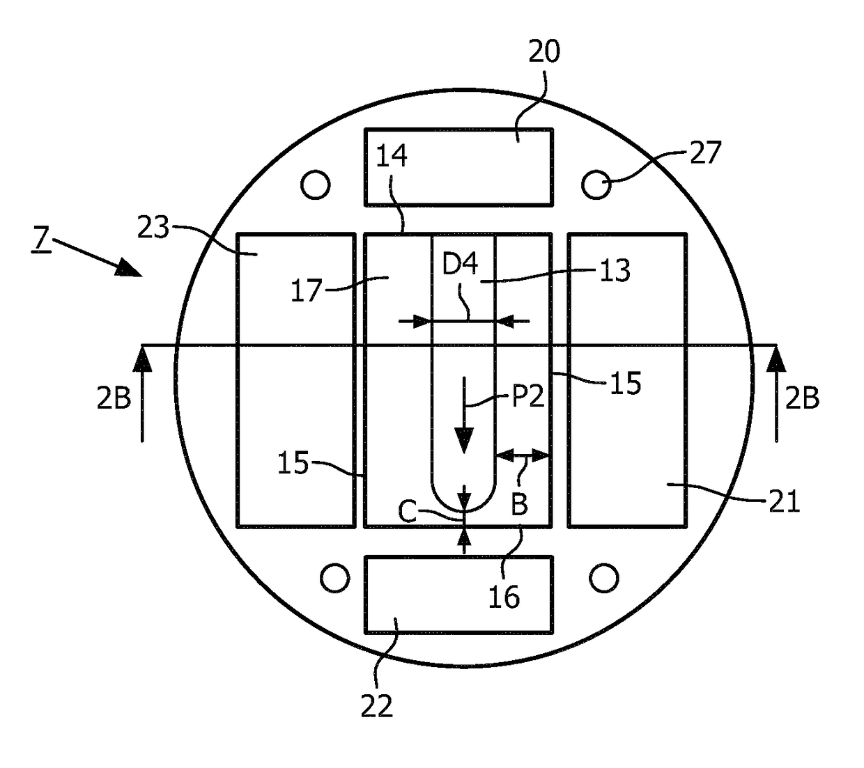
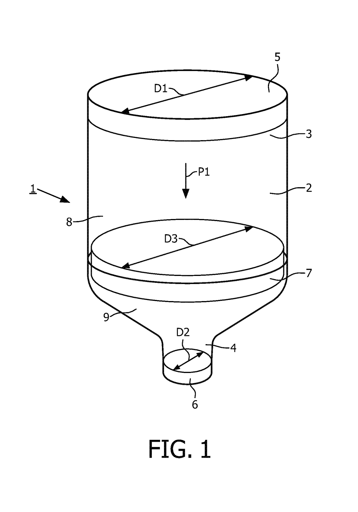
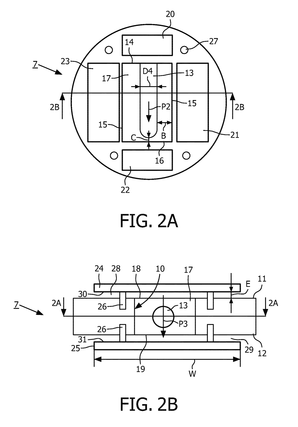
[0033]FIGS. 1-2B show different views of an optical fluid treatment device 1 according to the invention. The optical fluid treatment device 1 comprises a cylindrical fluid container 2 extending in a longitudinal direction P1. The cylindrical fluid container 2 is provided with a fluid inlet 3 and a fluid outlet 4. The fluid inlet 3 and the fluid outlet 4 each comprise a removable cover 5, 6. The cylindrical fluid container 2 has the shape of a bottle, wherein the diameter D1 of the fluid container 2 from the fluid inlet 3 to a position close to the fluid outlet 4 is relatively large, wherein near the fluid outlet 4 the cross section of the fluid container 2 gradually decreases to a much smaller diameter D2. In this manner, the cylindrical fluid container 2 can easily be filled with a fluid like water through the relatively large fluid inlet 3, whilst due to the relatively small diameter of the fluid outlet 4, the water will flow relatively slowly and in relatively small amounts out o...


PUM

PropertyMeasurementUnit
diameter D4aaaaaaaaaa
distanceaaaaaaaaaa
lengthaaaaaaaaaa

Abstract

An optical fluid treatment device comprising at least a holder provided with an aperture, a lamp device at least partly located in the aperture. The aperture comprises a fluid passage extending in a main fluid flow direction between a fluid inlet opening and a fluid outlet opening. The fluid passage extends at least partly along the lamp device, wherein the lamp device has an elongated shape extending substantially perpendicularly to the main fluid flow direction.

Description

CROSS-REFERENCE TO PRIOR APPLICATIONS[0001]This application is the U.S. National Phase application under 35 U.S.C. § 371 of International Application No. PCT / IE2014 / 059028, filed on May 5, 2014, which claims the benefit of European Patent Application No. 13168493.8, filed on May 21, 2013. These applications are hereby incorporated by reference herein.FIELD OF THE INVENTION[0002]The invention relates to[0003]an optical fluid treatment device comprising a) a holder provided with an aperture extending between a fluid inlet opening and a fluid outlet opening in a main fluid flow direction, said aperture being at least a part of a fluid passage, b) a fluid container extending in the main fluid flow direction, which fluid container is provided with at least a fluid inlet and a fluid outlet, wherein the holder is mounted in the fluid container between the fluid inlet and the fluid outlet, and c) a lamp device which, during operation, emits UV-radiation into the fluid passage.BACKGROUND OF ...

Claims


Application Information

Patent Timeline
Patent Type & Authority Patents(United States)
IPC IPC(8): C02F1/32
CPCC02F1/325C02F2201/009C02F2201/322C02F2201/326C02F2307/10C02F2201/3228C02F2303/04C02F2303/14C02F2201/3222Y02A20/212
Inventor GREUEL, GEORGSANGAMESWARAN, SANDEEP
Owner SIGNIFY HLDG BV
Learn More