Self-detaching anti-theft device with power removal station

a self-detachable, anti-theft technology, applied in the field of security tags, can solve the problems of inconvenient detachment of security tags using mobile pos units, none of these options are satisfactory for large-scale mobile pos adaption in the retail industry,

Active Publication Date: 2018-05-22
SENSORMATIC ELECTRONICS CORP
View PDF23 Cites 4 Cited by
  • Summary
  • Abstract
  • Description
  • Claims
  • Application Information

AI Technical Summary

Benefits of technology

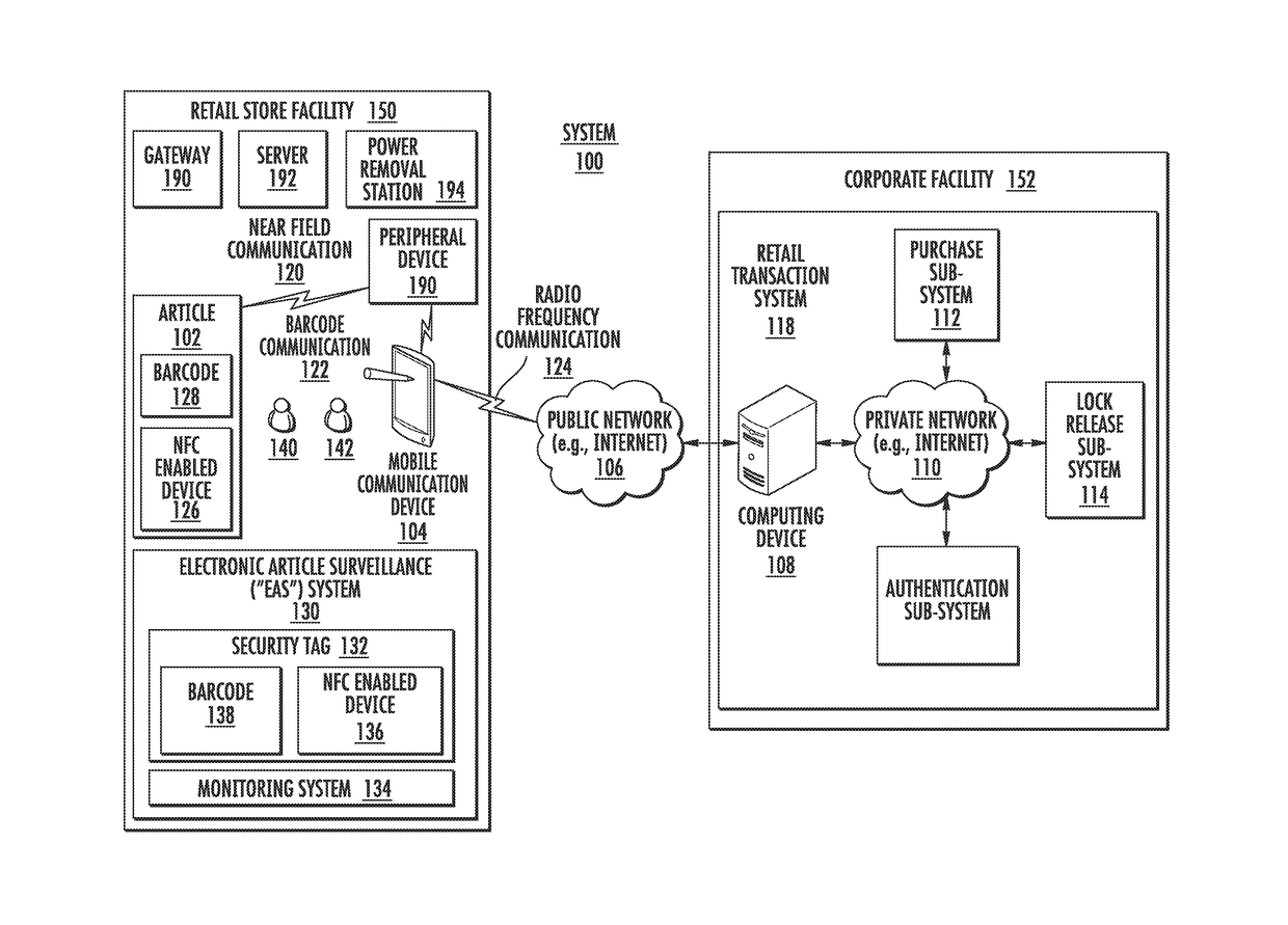
[0010]Other methods for operating a security tag involve: establishing an electrical connection between the PRS and the security tag; receiving by the PRS a signal sent from a computing device when a verification has been made that an article to which the security tag is attached has been successfully purchased; and supplying power from the PRS to the security tag in response to the PRS's reception of the signal so as to enable actuation of a mechanical component of the security tag, whereby a pin of the security tag transitions from an engaged position to an unengaged position without any human assistance or mechanical assistance by a device external to the security tag. The mechanical component is actuated upon authentication of a detach command sent from the PRS and received at the security tag.

Problems solved by technology

Currently, there is no convenient way to detach a security tag using a mobile POS unit.
None of these options is satisfactory for large scale mobile POS adaption in a retail industry.

Method used


Image

  • Self-detaching anti-theft device with power removal station
  • Self-detaching anti-theft device with power removal station
  • Self-detaching anti-theft device with power removal station

Examples


Embodiment Construction

[0023]It will be readily understood that the components of the embodiments as generally described herein and illustrated in the appended figures could be arranged and designed in a wide variety of different configurations. Thus, the following more detailed description of various embodiments, as represented in the figures, is not intended to limit the scope of the present disclosure, but is merely representative of various embodiments. While the various aspects of the embodiments are presented in drawings, the drawings are not necessarily drawn to scale unless specifically indicated.

[0024]The present invention may be embodied in other specific forms without departing from its spirit or essential characteristics. The described embodiments are to be considered in all respects only as illustrative and not restrictive. The scope of the invention is, therefore, indicated by the appended claims rather than by this detailed description. All changes which come within the meaning and range of...


PUM


Abstract

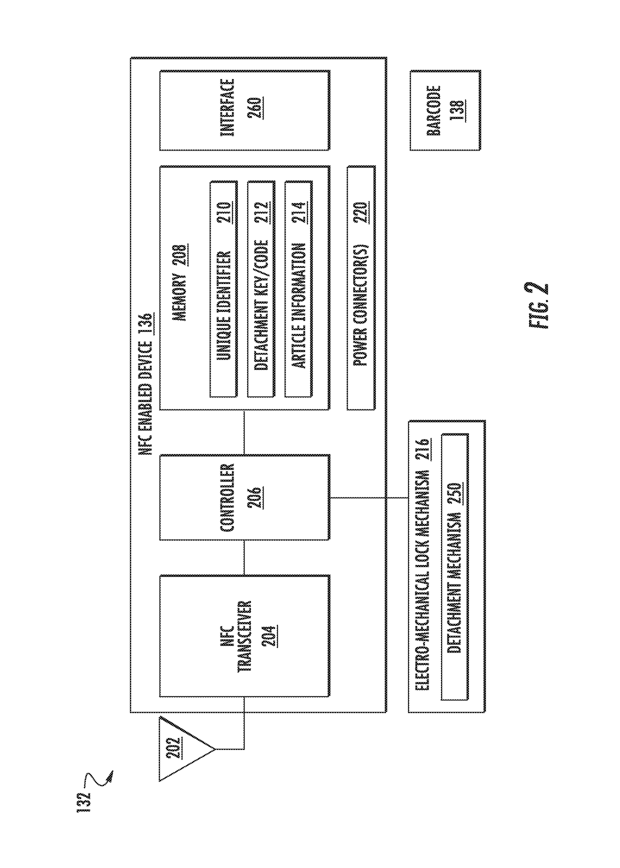
Systems and methods for operating a security tag. The methods involve: establishing an electrical connection between the security tag and an external Power Removal Station (“PRS”); performing operations by the security tag to authenticate a detach command sent from the external PRS; allowing power to be supplied from the external PRS to an electro-mechanical component of the security tag when the detach command is authenticated; and actuating the electro-mechanical component so that a pin of the security tag transitions from an engaged position to an unengaged position without any human assistance or mechanical assistance by a device external to the security tag.

Description

CROSS-REFERENCE TO RELATED APPLICATIONS[0001]This application claims priority to U.S. Patent Application No. 62 / 174,780, filed Jun. 12, 2015. The contents of the above application are incorporated by reference in its entirety.FIELD OF THE INVENTION[0002]This document relates generally to security tags used in Electronic Article Surveillance (“EAS”) systems. More particularly, this document relates to security tags and methods for facilitating a self-detaching of a security tag using a power removal station.BACKGROUND OF THE INVENTION[0003]A typical EAS system in a retail setting may comprise a monitoring system and at least one security tag or marker attached to an article to be protected from unauthorized removal. The monitoring system establishes a surveillance zone in which the presence of security tags and / or markers can be detected. The surveillance zone is usually established at an access point for the controlled area (e.g., adjacent to a retail store entrance and / or exit). If...

Claims


Application Information

Patent Timeline
Patent Type & Authority Patents(United States)
IPC IPC(8): G08B13/24E05B73/00
CPCG08B13/2434G08B13/242E05B73/0047E05B73/0017
Inventor CASANOVA, JOSEPEREZ, SERGIO M.CLARK, JOHN J.ZIRK, RANDY J.
Owner SENSORMATIC ELECTRONICS CORP
Why Eureka
Try Eureka