Hybrid metal compressor blades

a compressor blade and hybrid technology, applied in the field of hybrid metal compressor blades, can solve the problems that traditional manufacturing methods may not address incompatibility, and achieve the effects of extending the life of the compressor blade, enhancing the damage tolerance, and reducing manufacturing costs

Active Publication Date: 2018-05-29
GENERAL ELECTRIC CO
View PDF32 Cites 6 Cited by
  • Summary
  • Abstract
  • Description
  • Claims
  • Application Information

AI Technical Summary

Benefits of technology

[0007]The present invention provides a blade for gas turbine applications whereby the regional erosion and corrosion issues of the airfoil section of a compressor blade can be minimized. Another aspect of the invention provides a more efficient method to manufacture a compressor blade airfoil capable of providing the desired erosion and corrosion resistance as well as required mechanical properties on specific regions of a compressor blade.
[0009]The present invention uses Additive Manufacturing (AM) methods to implant the different desired materials at specific regions of the compressor blade to attain the required capabilities at each particular region while minimizing compatibility issues.
[0013]A significant advantage of the novel hybrid compressor blades disclosed herein includes providing tailored material compositions at specific regions of the compressor blade with the purpose of fulfilling the strength, erosion, and corrosion properties desired at each of the regions, thereby enhancing damage tolerance, erosion resistance, and corrosion resistance of the compressor blade, and extending the life of the compressor blade. An advantage of the novel manufacturing method disclosed herein is that the AM method allows the ability of having several material compositions in different regions on a single component, and addresses the material interface compatibility concerns by using transition zone and transition regions between different materials. Additional benefits include providing a method to produce a compressor blade that would not have been feasible or would have been difficult to produce using conventional methods. Conventional methods would require the use of multiple manufacturing processes to attain the same effect, which would increase the manufacturing cost. A single process method of manufacturing is believed to be more time efficient and economical.

Problems solved by technology

Traditional methods of manufacturing may not address the incompatibility issues that occur at the interface between the different materials used in forming the compressor blade.

Method used


Image

  • Hybrid metal compressor blades
  • Hybrid metal compressor blades
  • Hybrid metal compressor blades

Examples


Embodiment Construction

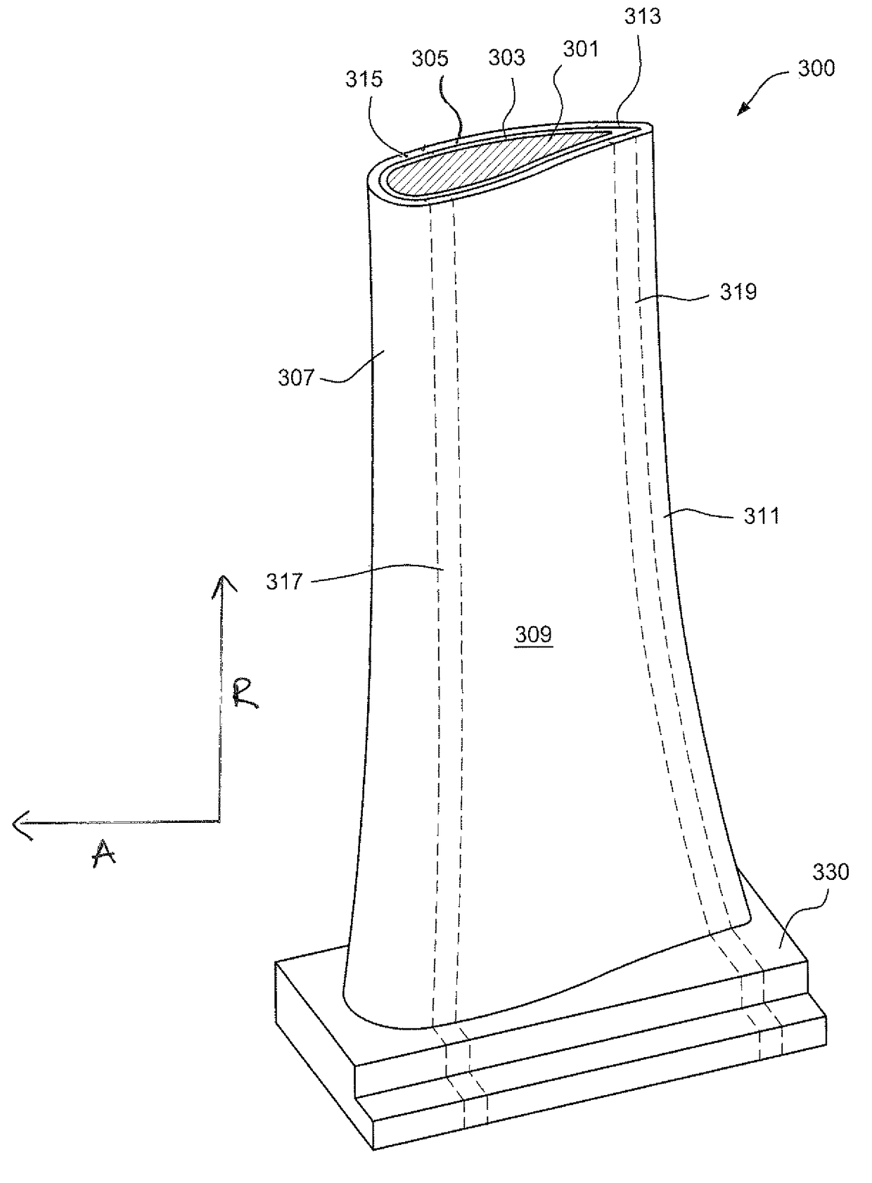
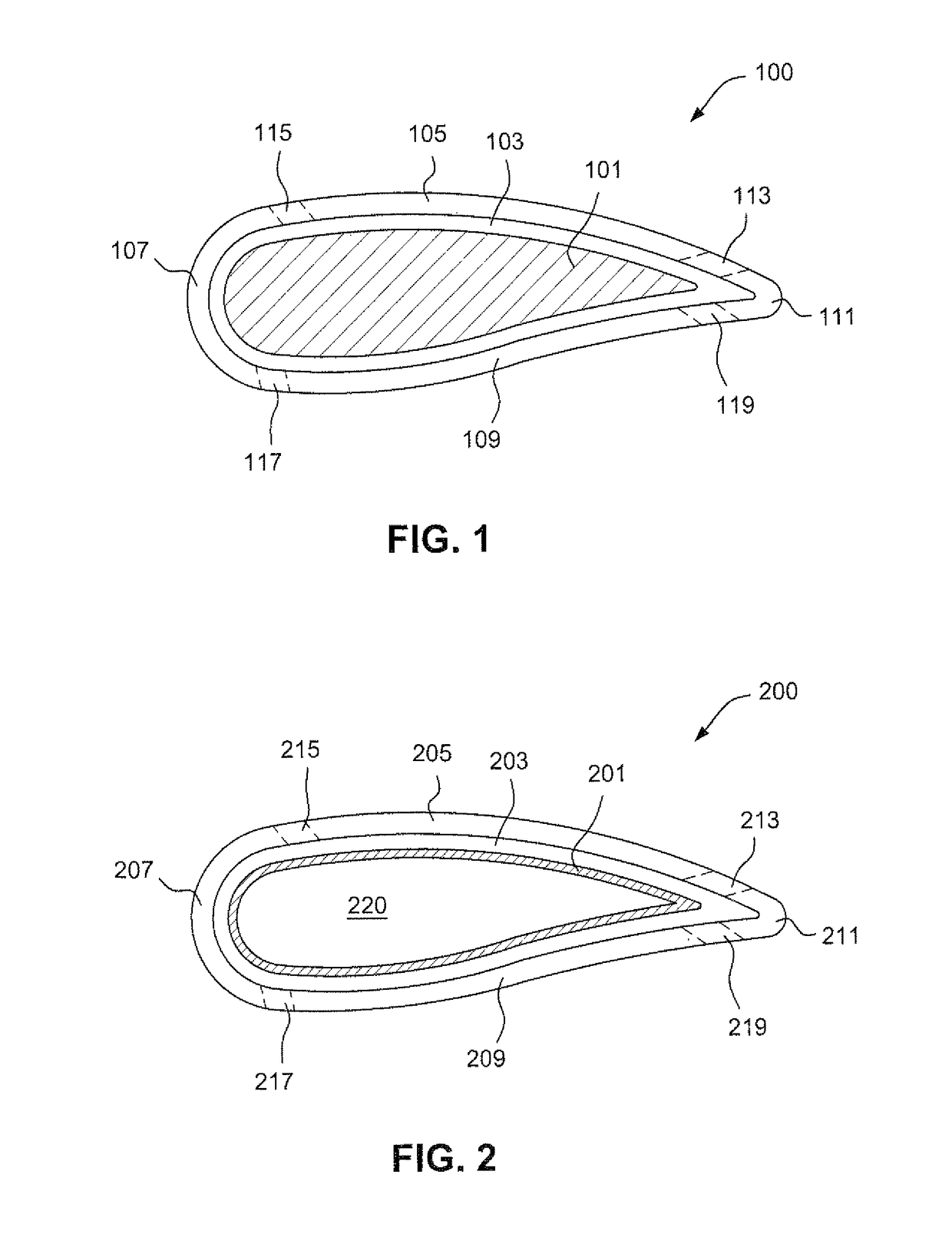
[0017]The present invention comprises a compressor blade that includes multiple outer shell regions containing different materials each selected to fulfill the different erosion, strength, corrosion, and durability requirements desired for their particular region of the compressor blade.

[0018]The core of the compressor blade may be one type of material or a combination of materials that provides the required strength to the compressor blade. An outer shell of the airfoil section of the compressor blade comprises various materials in different sections of the outer shell, the materials are chosen based on suitability to fulfill the most critical requirements of each specific region on the airfoil section. Each of the sections may include one single type of material or a combination of different types of materials to provide the desired level of corrosion and erosion resistance required at each of the particular section. The section may extend along the compressor blade in the radial ...


PUM

PropertyMeasurementUnit
pressureaaaaaaaaaa
concentrationsaaaaaaaaaa
volumeaaaaaaaaaa

Abstract

A hybrid compressor blade having an airfoil portion and a root portion that includes an outer shell comprised of one or multiple types of material that are each located at a predesignated section on the compressor blade, having at least one transition region between two different sections. The transition region is comprised of one or multiple layers with a compositional gradient based upon materials in the neighboring sections to provide a gradual transition from one section to another.

Description

[0001]The present invention discloses a hybrid gas turbine component, in particular a gas turbine hybrid compressor blade comprising an inner core and an outer shell having two or more regions of different materials. The outer shell includes one or more metals or metal alloys that are strategically placed on specific regions of the hybrid compressor blade.BACKGROUND OF THE INVENTION[0002]A gas turbine includes an inlet section that allows air intake into the gas turbine, and a compressor section that includes rotor and stator wheels, which draw in and compress air to be mixed with fuel in a combustor section downstream of the compressor section. Combustion gases generated in the combustor sections are used to turn turbine wheels in the turbine section to generate power. Located on the compressor rotor and stator wheels, gas turbine compressor blades are placed such that the blades are exposed to the inlet air and the heat produced during operation of the compressor. The compressor b...

Claims


Application Information

Patent Timeline
Patent Type & Authority Patents(United States)
IPC IPC(8): F01D5/14B22F5/04F04D29/32F01D5/28B23K26/342B33Y10/00
CPCF04D29/324B22F5/04B23K26/342F01D5/147F01D5/288F01D5/28F05D2230/31B22F2207/00B33Y10/00F04D29/023F04D29/26F05D2240/30F05D2300/17B22F2999/00B22F10/25B22F7/06B22F10/38B22F2207/01B22F10/28C22C1/04B22F2998/10B33Y80/00Y02P10/25
Inventor MORICCA, MARIA DEL PILAR
Owner GENERAL ELECTRIC CO
Why Eureka
Try Eureka