
Device for displaying and updating trajectory patterns, in particular SAR trajectory patterns

Inactive Publication Date: 2018-05-29
THALES SA
View PDF10 Cites 0 Cited by
  • Summary
  • Abstract
  • Description
  • Claims
  • Application Information

AI Technical Summary

Benefits of technology

This invention is about a device that displays patterns, which can be updated by an operator through the movement of control points. The device comprises at least display means and means for calculating and memorizing the positions of the pattern points, each pattern comprising a set of control points. The technical effect of this invention is to enable the operator to modify the position, orientation, and form of the patterns through interactions with the device, providing greater flexibility and accuracy in creating and executing trajectory patterns. Additionally, the invention can incorporate external parameters and data from sensors to optimize the patterns. The device can be placed on board an aircraft or transmitted to a flight management system (FMS) for use in search and rescue missions.

Problems solved by technology

In particular, the drawbacks of these solutions are:
time wasted by the operator responsible for calculating the technical parameters.
Specifically, even with an FMS, these parameters are still calculated manually and these calculations are not simple, since they depend on multiple technical, geographic or environmental parameters such as the geographic area to be covered, the transit time, the altitude of the aircraft, the weather, the sea conditions or the flight speed;
This lack of representation leads to wasted time for the operator, who must re-enter a trajectory if he or she considers the latter not to be optimal with respect to the search area;
a lack of direct relationship between the SAR pattern and the current mission.
This leads to wasted time for the operator, who must re-enter a trajectory if he or she considers the latter not to be optimal with respect to the search area;
wasted time for the pilot who must concentrate on flight management rather than on successfully accomplishing the mission;
lastly, these technical parameters have to be entered manually, which leads to wasted time for an operator.
It is therefore apparent that the cognitive load linked to the operations is substantial and takes up a lot of the operator's time.

Method used


Image

  • Device for displaying and updating trajectory patterns, in particular SAR trajectory patterns
  • Device for displaying and updating trajectory patterns, in particular SAR trajectory patterns
  • Device for displaying and updating trajectory patterns, in particular SAR trajectory patterns

Examples


Embodiment Construction

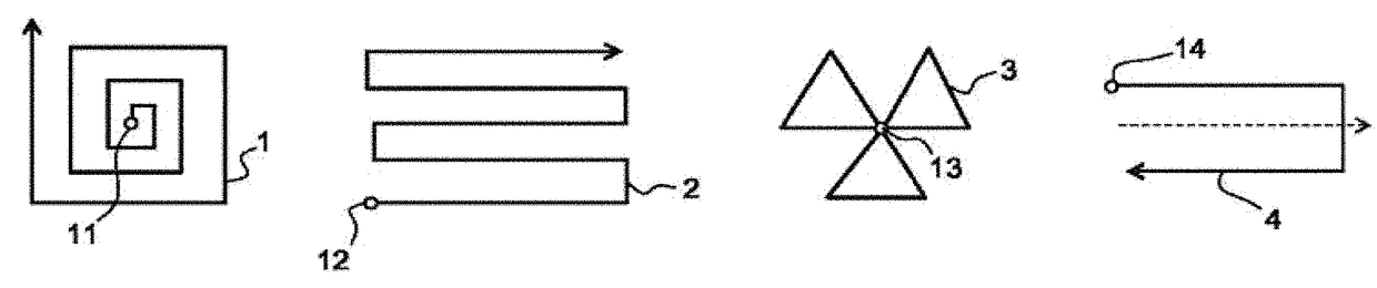
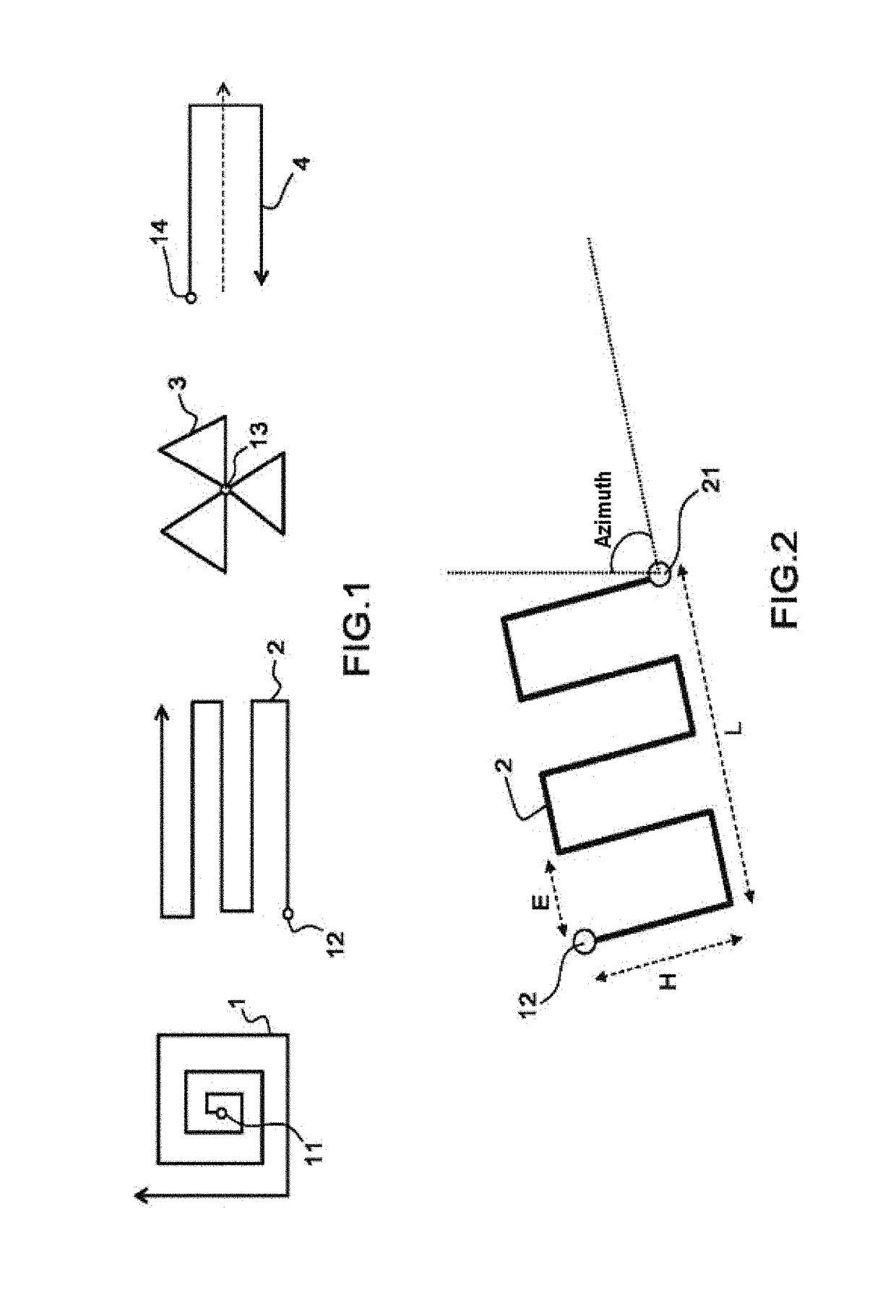
[0037]FIG. 1 shows four patterns 1, 2, 3, 4 describing SAR trajectories generally used in the prior art. These patterns define search routes to be followed by the aircraft in order to carry out the search. The are used according to the conditions and the nature of the search. These trajectory patterns each have a certain number of technical parameters that have to be adjusted for each mission, starting with the choice of pattern: a pattern 1 in the form of an extended square, a pattern 2 in the form of a ladder, a sectored pattern 3 or a tracking pattern 4, other patterns being possible. In particular, the technical parameters to be adjusted are the following:

[0038]the position of the entry point 11, 12, 13, 14, defined by its latitude and longitude;

[0039]the position of the exit point;

[0040]the width and / or length of the pattern;

[0041]the orientation of the pattern, defined by an angle with respect to north.

[0042]These parameters must be calculated and entered by the operator in or...


PUM


Abstract

A device comprises display means and means for calculating and memorizing the positions of points forming patterns being capable of being updated by an operator, the position, orientation and the form of a pattern being defined by a set of technical parameters. Each pattern comprises a set of control points, the function of a control point being, by virtue of its movement, to modify at least one technical parameter, a trajectory pattern modification being carried out through an interaction in which the operator moves at least one control point.

Description

CROSS-REFERENCE TO RELATED APPLICATIONS[0001]This application is a National Stage of International patent application PCT / EP2015 / 061068, filed on May 20, 2015, which claims priority to foreign French patent application No. FR 1401152, filed on May 21, 2014, the disclosures of which are incorporated by reference in their entirety.FIELD OF THE INVENTION[0002]The present invention relates to a device for displaying and updating trajectory patterns, in particular SAR trajectory patterns. The invention ties in to the technical field of civilian or military mission avionics. In particular, it relates to the execution of aircraft-based search and rescue (SAR) missions. The invention may also be applied to seagoing vessels for the same type of mission.BACKGROUND[0003]In order to find a person or vessel lost at sea or on land, an aircraft must follow a pattern describing a search pattern, or SAR pattern, which will be referred to as a SAR trajectory, or more simply a SAR pattern, hereinafter...

Claims


Application Information

Patent Timeline
IPC IPC(8): G01C21/00G08G5/00
CPCG08G5/0021G08G5/0039G08G5/0034G01C23/00
Inventor ARNEAU, DAVIDDUPONT, GUILLAUME
Owner THALES SA
Features
  • Generate Ideas
  • Intellectual Property
  • Life Sciences
  • Materials
  • Tech Scout
  • Unparalleled Data Quality
  • Higher Quality Content
  • 60% Fewer Hallucinations
Learn More