
Methods of enabling base station functionality in a user equipment

a technology of user equipment and base station, applied in the field of wireless multimedia telecommunications, can solve the problems of cellular coverage not being able to provide the desired services, devices are not without limitations, and are usually unable to make voice calls

Active Publication Date: 2018-05-29
PARALLEL WIRELESS
View PDF32 Cites 2 Cited by
  • Summary
  • Abstract
  • Description
  • Claims
  • Application Information

AI Technical Summary

Benefits of technology

[0027]In embodiments of this invention, user equipment has the ability to execute a reverse banding functionality wherein hardware normally used for receiving signals becomes hardware that is used for transmitting and vice versa. In some embodiments, the user equipment could have additional battery power, solar recharging capabilities, and other means of enhancing normal consumer-grade power characteristics of user equipment. In many embodiments, the user equipment could be a smart phone or other telephonic device. But in some embodiments tablets, laptops and so forth could be used as well.

Problems solved by technology

Although cellular network coverage in urban areas is often strong, there are many situations in which cellular coverage falls short of being able to provide the desired services.
But either way, when a smart phone is out of range of a base station, it is usually unable to make a voice call because it does not have connectivity to the core network.
While land-mobile radios and dual-use phones can facilitate voice communication in the absence of a connection to a base station, and by extension, to the core network, these devices are not without their limitations.
Devices that move outside of the range of the LMR network become unreachable.
Dual-use handsets are limited by the range of the base station or access point providing connectivity to the core network.

Method used


Image

  • Methods of enabling base station functionality in a user equipment
  • Methods of enabling base station functionality in a user equipment
  • Methods of enabling base station functionality in a user equipment

Examples


Embodiment Construction

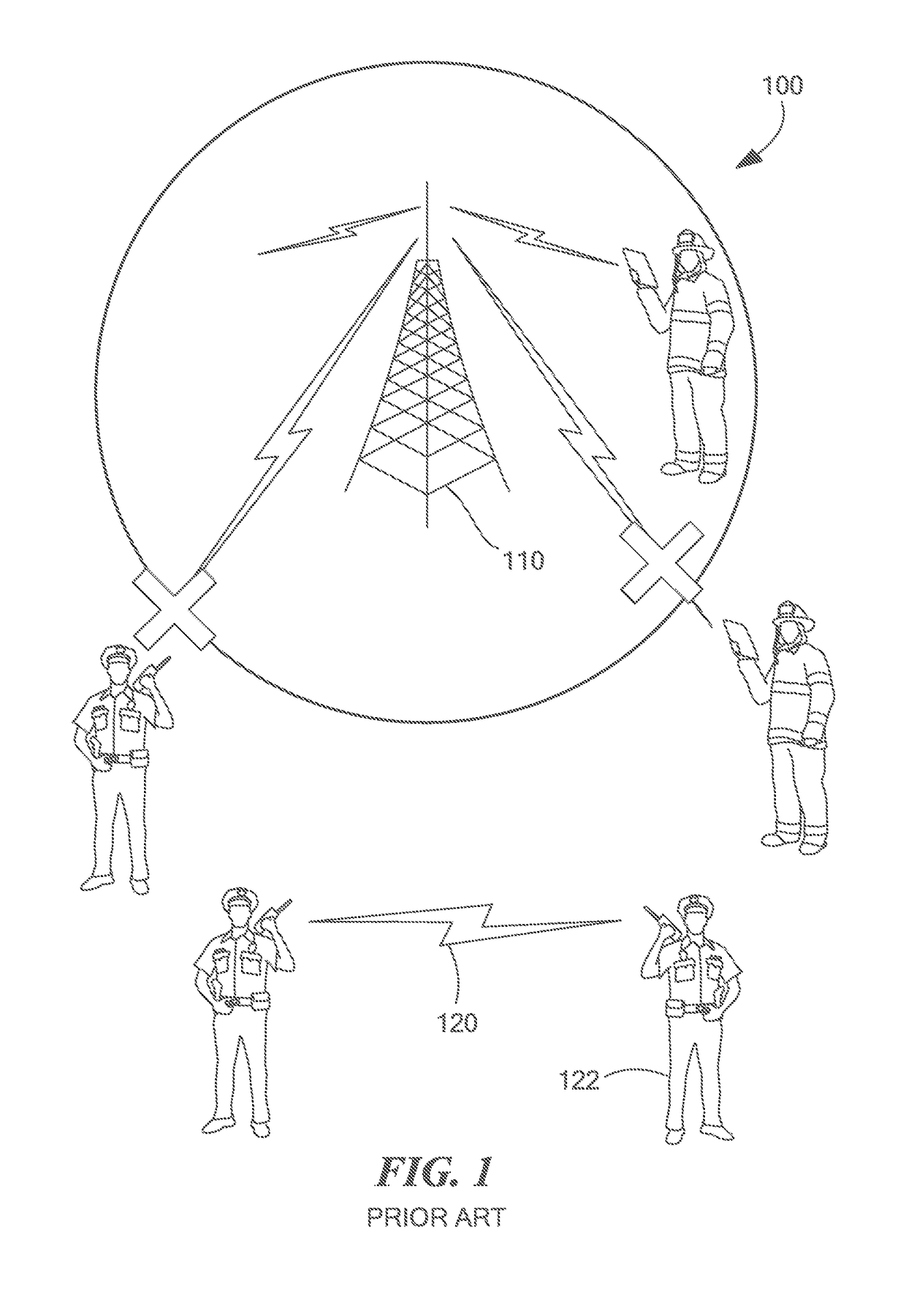
[0074]FIG. 1 shows an exemplary diagram of a prior art public safety communication network100 that facilitates two types of communication—either through a tower 110 or peer-to-peer 120. In either of these communication modes, the public safety officer's radio must be within range of the tower 110, or of his peer 122. Being within range of a receiving radio or base station is an inherent limitation of all wireless communication networks. Some of the drawbacks of tower-based infrastructure are discussed in the background section.

[0075]In the public safety communication network 100, range problems are further compounded in the United States by the fact that most public safety communication networks 100 are owned and operated by individual towns, cities, municipalities, and the like. This results in a lack of uniformity nationwide and an inability to leverage infrastructure from surrounding localities. Some of the public safety communications networks 100 in various countries are privat...


PUM


Abstract

In this invention, we disclose methods for enabling ad hoc cellular base station functionality within a user equipment when the connection quality between a base station and the user equipment is limited or nonexistent. These methods include measuring a connection quality between a user equipment and its serving base station. If the connection quality is below a threshold, the user equipment can enable its internal ad hoc cellular base station functionality. This is done by running a software within the user equipment that (a) checks the connection quality periodically, and (b) enables ad hoc cellular base station functionality of the connection threshold dips below a certain value. In one embodiment, that threshold could be the same threshold value that a user equipment would use if it were making a decision to handoff to another base station based on poor connection quality.

Description

CROSS-REFERENCE TO RELATED APPLICATIONS[0001]This application claims priority to the following U.S. Provisional Patent Applications: No. 61 / 787,832, entitled “Method of Directly Connecting UEs,” filed Mar. 15, 2013; and U.S. Provisional Patent Application No. 61 / 790,105 entitled “Forming Backhaul Links Using Wireless User Equipment,” filed on Mar. 15, 2013 the entire contents of which are hereby incorporated by reference.FIELD[0002]The present invention relates generally to wireless multimedia telecommunications. More specifically, this invention relates to methods of providing ad hoc cellular base station functionality using user equipment.BACKGROUND[0003]Although cellular network coverage in urban areas is often strong, there are many situations in which cellular coverage falls short of being able to provide the desired services. Some examples of these shortcomings are: lack of in-building coverage, masking in urban canyons, rural areas without coverage, geographic topology that i...

Claims


Application Information

Patent Timeline
Patent Type & Authority Patents(United States)
IPC IPC(8): H04B7/00H04W36/30H04B17/309H04L12/26H04W84/18
CPCH04W76/23H04B17/309H04W36/30H04L43/16H04W84/18H04W36/03
Inventor MISHRA, RAJESH KUMARAGARWAL, KAITKIPAPA, STEVEN PAULDONEPUDI, SRIDHAR
Owner PARALLEL WIRELESS
Learn More