
Electronic device for changing charging parameter depending on state of battery and control method thereof

Active Publication Date: 2018-10-18
SAMSUNG ELECTRONICS CO LTD
View PDF0 Cites 6 Cited by
  • Summary
  • Abstract
  • Description
  • Claims
  • Application Information

AI Technical Summary

Benefits of technology

The patent describes a method for charging electronic devices' batteries efficiently while considering the battery's state and preventing overcharging or performance loss. The method is achieved through a charging circuit that determines the battery's state and adjusts the charging parameters accordingly. This can be done by a measurement circuit that collects data associated with the battery's state. The main processor and sub-processor of the electronic device complement each other to calculate the charging parameters, reducing additional power consumption. The technical effects are improved battery charging efficiency, increased battery safety, and better user experience.

Problems solved by technology

Conventionally, however, it is difficult to install a battery having constant charging capacity due to space restrictions.
However, such fast battery conventionally causes as a battery degradation phenomenon of reduced battery capacity, thus reducing a state of health (SOH) of the battery.
That is, a battery may deteriorate in capacity (or performance) due to charging repetition, and in turn, hardware in an electronic device may operate abnormally.
Since battery replacement is difficult, the entire electronic device should be replaced.
However, it is difficult for a user to verify a state of the battery and charge the battery in a proper time and environment depending on the verified state.
Since a state of the battery continues to change while the battery is charged, it is difficult to efficiently manage the battery.
In addition, a constant current constant voltage (CCCV) charging method for supplying a constant current until a predetermined time in consideration of an SOC of the battery and supplying a constant voltage after the predetermined time may have a limitation in enhancing battery charging efficiency, particularly since the state of the battery continues to change depending on a charging cycle of the battery.

Method used


Image

  • Electronic device for changing charging parameter depending on state of battery and control method thereof
  • Electronic device for changing charging parameter depending on state of battery and control method thereof
  • Electronic device for changing charging parameter depending on state of battery and control method thereof

Examples


Embodiment Construction

[0026]Embodiments of the present disclosure will be described with reference to accompanying drawings. Accordingly, those of ordinary skill in the art will recognize that modification to the embodiments described herein can be variously made without departing from the scope and spirit of the present disclosure. With regard to description of the drawings, similar elements may be marked by similar reference numerals.

[0027]Embodiments of the present disclosure and terms used herein are not intended to limit the technologies described in the present disclosure to specific embodiments, and it should be understood that the embodiments and the terms include modifications, equivalents, and / or alternatives on the corresponding embodiments described herein. With regard to description of drawings, similar elements may be marked by similar reference numerals. The terms of a singular form may include plural forms unless otherwise specified.

[0028]In the disclosure, the expressions “A or B”, “at l...


PUM


Abstract

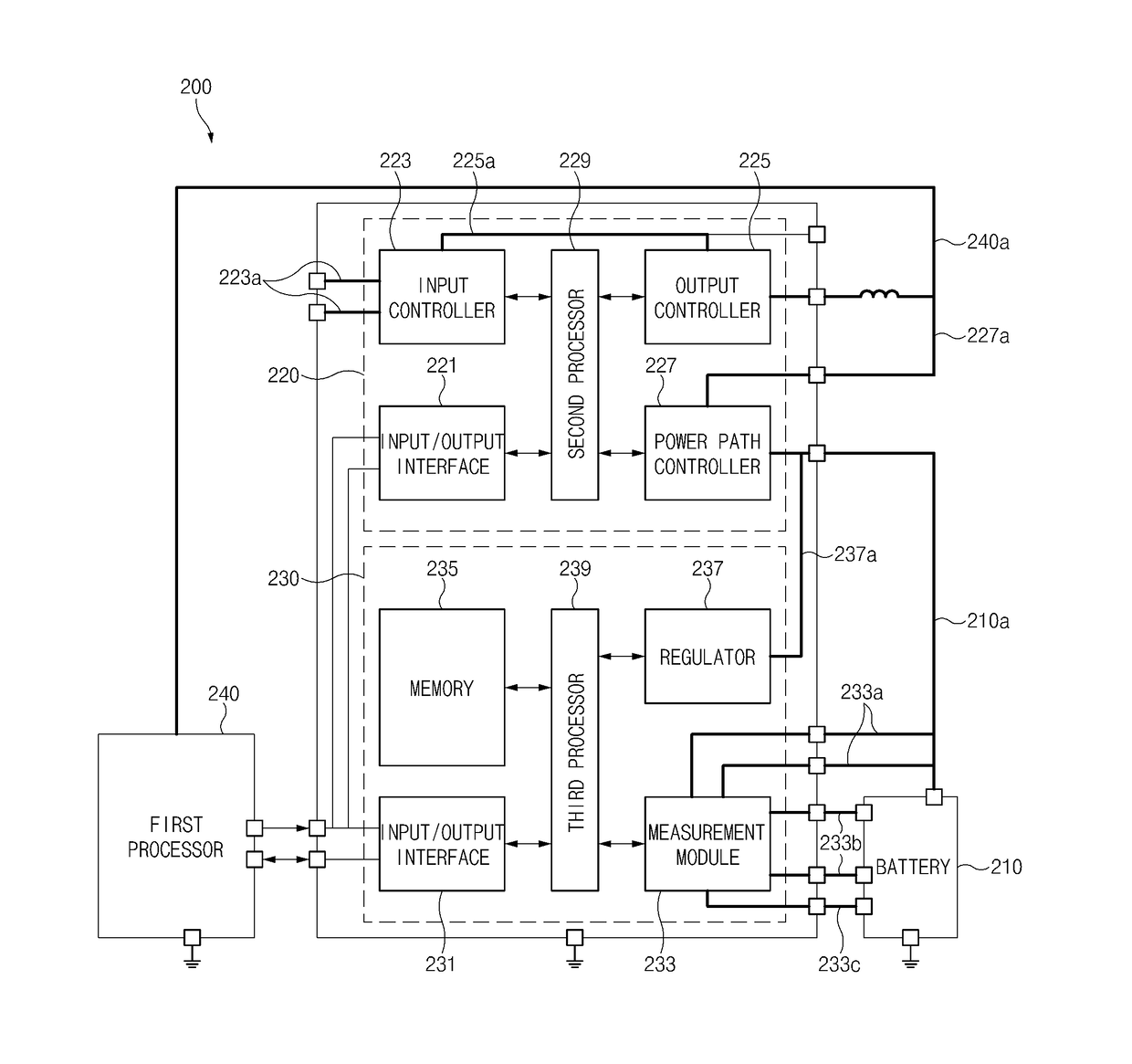
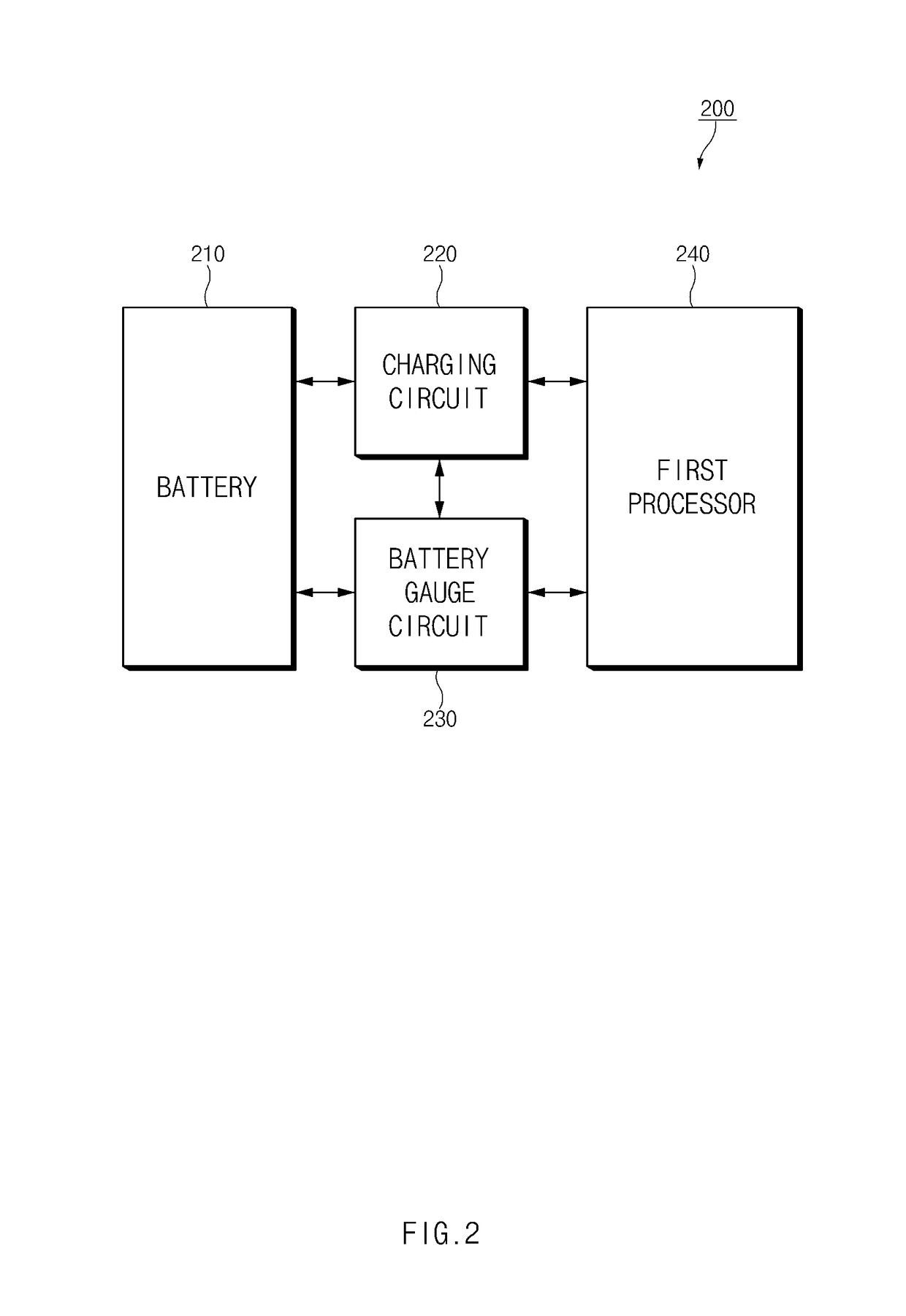
Disclosed is an electronic device including a battery, a charging circuit configured to charge the battery, a measurement circuit configured to measure a state of the battery, and a processor configured to be electrically connected with the battery, the charging circuit, and the measurement circuit, to charge the battery using the charging circuit set by a first charging parameter, determine state information corresponding to a state of the battery based on data associated with the state of the battery obtained using the measurement circuit, determine a second charging parameter for reducing loss of a capacity of the battery based on the state information, and charge the battery using the charging circuit set by the second charging parameter.

Description

CROSS-REFERENCE TO RELATED APPLICATION(S)[0001]This application is based on and claims priority under 35 U.S.C. § 119 to Korean Patent Application No. 10-2017-0048772, filed on Apr. 14, 2017, in the Korean Intellectual Property Office, the disclosure of which is incorporated herein by reference its entirety.BACKGROUND1. Field[0002]The disclosure relates generally to an electronic device, and more particularly, to a method for controlling a state of charge (SOC) of a battery of an electronic device.2. Description of Related Art[0003]An electronic device, such as a smartphone, a television (TV), or a tablet personal computer (PC), includes highly specified hardware that conveniently provides various services to a user. Such devices, therefore, require a battery capable of supplying sufficient power to operate this hardware. In general, the electronic device may include a battery and may receive power from the battery, in order for the internal hardware to operate. When the battery is ...

Claims


Application Information

Patent Timeline
IPC IPC(8): H02J7/00G06F1/26
CPCH02J7/0072G06F1/263H02J7/00714H02J7/007182H02J7/007194G01R31/382H02J7/00H02J7/0071
Inventor BATTLE, JASON MICHAELYADU, ANKITMANDLI, ARAVINDA REDDYHARIHARAN, KRISHNAN SEETHALAKSHMYTAGADE, PIYUSHPATIL, RAJKUMAR SUBHASH
Owner SAMSUNG ELECTRONICS CO LTD
Learn More