Circuit system for coupling an electrical control unit to a voltage supply, and electrical control unit

Inactive Publication Date: 2019-07-25
ROBERT BOSCH GMBH
View PDF0 Cites 0 Cited by
  • Summary
  • Abstract
  • Description
  • Claims
  • Application Information

AI Technical Summary

Benefits of technology

The present invention provides a device for coupling a voltage supply with an electrical energy store that largely avoids the occurrence of high electric currents. This is achieved by using a control unit with an electrical energy store and a switching element, such as a semiconductor switch or a mechanical switch. A high-impedance electrical resistor is furthermore provided parallel to the switching element to allow a low electrical current to flow between the electrical energy store and the voltage source when the switching element is open. This low current is sufficient to charge the electrical energy store. The device is simple and cost-effective, with no additional components required. The system as a whole is safer and more efficient. The placement of an electrical resistor parallel to the switching element ensures that no significant current flow occurs during a short-circuit in the control unit. The electrical resistor is dimensioned as large as possible to keep the currents across the path low, while still allowing charging of the capacitor within a reasonable time. The control unit can be activated using an activation signal and is able to be deactivated or set to a readiness / standby mode. The first and second input connections of the device for coupling the control unit with the voltage supply are electrically coupled with a vehicle electrical system of a motor vehicle, which is supplied by a 12 volt or 24 volt battery. This reduces voltage drops due to the limited capacity of the batteries and ensures a stable voltage supply.

Problems solved by technology

This electrical current is limited only by line resistances, line inductivities and possibly further parasitic components.
In the case of electrical energy stores having a large capacity, this normally leads to a high cut-in current.
Since this high cut-in current may possibly lead to significant loading of the electrical voltage source, circuit systems are usually provided which limit a cut-in current during the connection of the electrical energy store to a voltage source.

Method used


Image

  • Circuit system for coupling an electrical control unit to a voltage supply, and electrical control unit
  • Circuit system for coupling an electrical control unit to a voltage supply, and electrical control unit

Examples


Embodiment Construction

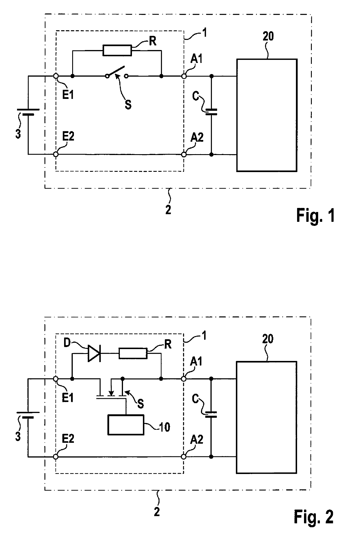
[0026]FIG. 1 shows a schematic illustration of an electrical control unit 2 according to one specific embodiment. Electrical control unit 2 may be any electrical control unit, in particular an electrical control unit for a motor vehicle. Such control units 2 may be used for the control of electrical drive systems in electric or hybrid vehicles, for example. In addition, various other electrical control units are possible, e.g., electrical control units for different electric motors, in particular in a motor vehicle. However, electrical control units for other application purposes such as for the control of an airbag system in a vehicle or similar purposes are also possible.

[0027]Control unit 2 includes a control device 20, for example. This control device 20, for instance, may be configured to receive and evaluate various input signals. In addition, depending on the application case, control device 20 is able to generate suitable control signals based on the processing results of co...


PUM


Abstract

A device for coupling a control unit with a voltage supply. An electrical connection between the voltage supply and the electrical control unit may be opened / closed with a switching element. An electrical resistor, which allows for a limited current flow from the voltage supply to the electrical control unit even when the switching element is open, is parallel to the switching element. Thus, an electrical energy store, such as a capacitor or a similar device, which is to buffer the input voltage at the electrical control unit, is chargeable even when the switching element is open. This is to avoid adverse effects caused by the charging of a capacitor at the input of the control unit when the switching element is closed.

Description

FIELD OF THE INVENTION[0001]The present invention relates to a device for coupling an electrical control unit with a voltage supply, and to an electrical control unit having such a device. In addition, the present invention relates to an electrical drive system having an electrical control unit.BACKGROUND INFORMATION[0002]Numerous electronic circuits such as electrical control units have an electrical energy store in the form of an electrical capacity. Especially in many control units in the automotive field, such electrical energy stores are provided in the form of capacitors or similar devices. Such electrical energy stores make it possible to compensate for voltage fluctuations of a supplying electrical energy source or possibly also to maintain the function of the control unit for a predefined period of time in the event that the connected voltage source fails or is cut off for reasons of safety.[0003]Such electrical energy stores are usually made up of one or a plurality of cap...

Claims


Application Information

Patent Timeline
IPC IPC(8): H02H9/00H02H7/06
CPCH02H9/001H02H7/065H02H7/06
Inventor HEY, ALEXANDERWINGERT, FABIANBUECKER, MARTINLIMBACH, ODARIEDEL, SIMONHOESS, STEFANSAILE, THOMASWEEBER, VOLKER
Owner ROBERT BOSCH GMBH
Why Eureka
Try Eureka