Transformer test platform

A test platform and transformer technology, applied in the field of power electronics, can solve the problems of complicated transformer testing and large active power loss, and achieve the effects of small active power loss, energy saving and convenient operation.

Inactive Publication Date: 2016-06-29
STATE GRID CORP OF CHINA +1
View PDF8 Cites 2 Cited by
  • Summary
  • Abstract
  • Description
  • Claims
  • Application Information

AI Technical Summary

Problems solved by technology

[0004] The purpose of the present invention is to propose a transformer test platform for the deficiencies of the prior art and to overcome the shortcomings of the existing transformers, which are cumbersome to test and have large active power losses.

Method used


Image

  • Transformer test platform
  • Transformer test platform
  • Transformer test platform

Examples


Embodiment 1

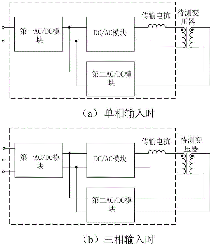
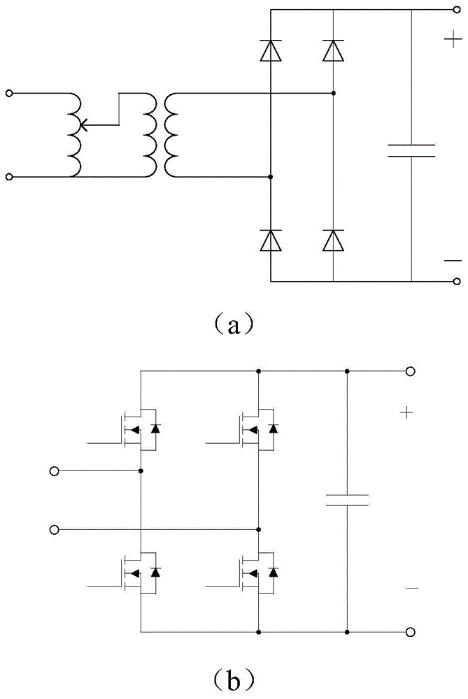
[0025] The system block diagram of this embodiment is as follows figure 1 (a) shown. The external single-phase power supply is connected to the input terminal of the first AC / DC module, the output terminal of the first AC / DC module is connected to the input terminal of the DC / AC module and the DC output terminal of the second AC / DC module, and the DC / AC module’s One end of the output terminal is connected to the input side of the transformer under test through the transmission reactance, and the input side of the second AC / DC is connected to the output side of the transformer. The positive voltage output terminal of the second AC / DC module is connected to the positive voltage output terminal of the first AC / DC module, and the negative voltage output terminal of the second AC / DC module is connected to the negative voltage output terminal of the first AC / DC module end connected.

[0026] Its operation mode is as follows: the external single-phase alternating current is convert...

Embodiment 2

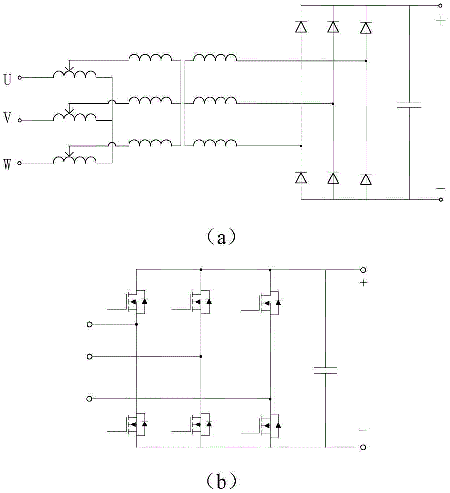
[0035] The system block diagram of this embodiment is as follows image 3 (a) shown. The external three-phase power supply is connected to the input terminal of the first AC / DC module, the output terminal of the first AC / DC module is connected to the input terminal of the DC / AC module and the DC output terminal of the second AC / DC module, and the DC / AC module’s One end of the output terminal is connected to the input side of the transformer under test through the transmission reactance, and the input side of the second AC / DC is connected to the output side of the transformer. The positive voltage output terminal of the second AC / DC module is connected to the positive voltage output terminal of the first AC / DC module, and the negative voltage output terminal of the second AC / DC module is connected to the negative voltage output terminal of the first AC / DC module end connected.

[0036] Its operation mode is: the external three-phase alternating current is converted into adjus...


PUM


Abstract

The invention discloses a transformer test platform, and belongs to the technical field of electronic power and electronics. The transformer test platform disclosed by the invention is composed of a first AC/DC module, a DC/AC module, a transmission reactor and a second AC/DC module. The first AC/DC module converts external AC power into DC power, and DC voltages are adjustable; the DC/AC module converts the DC power into the AC power, and the AC power is connected with the primary winding of a transformer to be tested after passing through the transmission reactor; and after secondary-winding AC power of the transformer to be tested is output, the secondary-winding AC power is converted into AC power through the second AC/DC module for connection with the DC output side of the first AC/DC module. The test platform provided by the invention can conveniently adjust voltages, frequencies and currents of the transformer to be tested, is small in loss and is economical and environmental friendly.

Description

technical field [0001] The invention belongs to the technical field of power electronics, and mainly relates to a transformer test platform. Background technique [0002] With the development of high-power switching power supply, frequency converter, photovoltaic inverter, power electronic transformer, electric vehicle charging pile and other power electronic products, transformers (especially 10-200KHz high-frequency transformers) are widely used, and their design put forward higher requirements. For this reason, it is necessary to customize the transformer according to different conditions (such as power, frequency, voltage, current, etc.), which brings great challenges to the development and testing of transformers. [0003] The traditional test method for transformers is to apply AC power with a specified frequency after rectification and inversion to the primary side of the transformer, and the secondary side is connected to a resistive load. It has the following disad...

Claims


Application Information

Patent Timeline
Patent Type & Authority Applications(China)
IPC IPC(8): G01R31/00
CPCG01R31/00
Inventor 董长城侯凯骆健王志刚辛甜卢文兵何安然徐建松武迪吕晓飞王皓
Owner STATE GRID CORP OF CHINA
Why Eureka
Try Eureka