Adjustable mounting for a post system

a post system and adjustment technology, applied in the field of adjustment of post mountings, can solve the problem of no teaching of mail or newspaper box mounting to the mounting post in the deike paten

Inactive Publication Date: 2000-02-08
WEST RONALD R
View PDF21 Cites 31 Cited by
  • Summary
  • Abstract
  • Description
  • Claims
  • Application Information

AI Technical Summary

Benefits of technology

It is a principal object of the present invention in an adjustable post mounting system to provide a system for mounting a straight post to a ground anchor that includes a capability for adjusting and maintaining the post to a desired vertical attitude relative to the ground surface.
Another object of the present invention is to provide an arrangement of a ground mount for coupling to a post, the combination to provide a tight and secure coupling.
Still another object of the present invention is to provide a simple adjustable mounting for a post system where the individual components can be produced from an inexpensive and durable material, such as plastic, which system provides for ease of installation by a person with only simple tools and requires little or no mechanical skills.
The present invention is in an inexpensive, simple to install and yet durable post system. The post system includes a ball section or portion of an adjustable mount that can be fitted onto a ground stake that is to be driven into the earth, can be mounted to cement, or the like. The ball portion of the adjustable mount is for positioning in a seat that is for coupling to a post insert or into a post end. Both the post and post insert attitude to the vertical is adjustable and is maintained by a mounting that utilizes single nut and bolt fastener.
A second embodiment of which adjustable mounting involves a pair of sloping or tapered washers that are center holed to fit together as a stack and receive a bolt therethrough. Which bolt is also fitted through holes formed in opposing plates that are secured respectively, across the post insert bottom and the ground stake or anchor top surface. The washers fitted over one another have their tapered surface arranged juxtaposition to one another. The rotation of one of which washers over the other therefore increases or decreases, respectively, the thickness of the opposite washer stack edge. The washer stack top surface can therefore be angled to the vertical relative to its lower surface. Which angle translates to a tilt of the post, and is maintained by turning a nut over which bolt threaded end.
The post insert is for receiving an end of a post, such as a post for mounting a mail box, fitted thereover. For which coupling, screw holes are formed through both the post and post insert that, with the post telescoped thereon, align to receive screws turned therethrough, securing the components together. Resilient spacers are preferably arranged between the opposing surfaces of which post and post insert to provide a tight coupling. Alternatively, the ball seat can be imbedded directly into the bottom of the post to eliminate the post insert.

Problems solved by technology

Further, there is no teaching of a mail or newspaper box mounting to the mounting post in the Deike patent.

Method used


Image

  • Adjustable mounting for a post system
  • Adjustable mounting for a post system
  • Adjustable mounting for a post system

Examples


Embodiment Construction

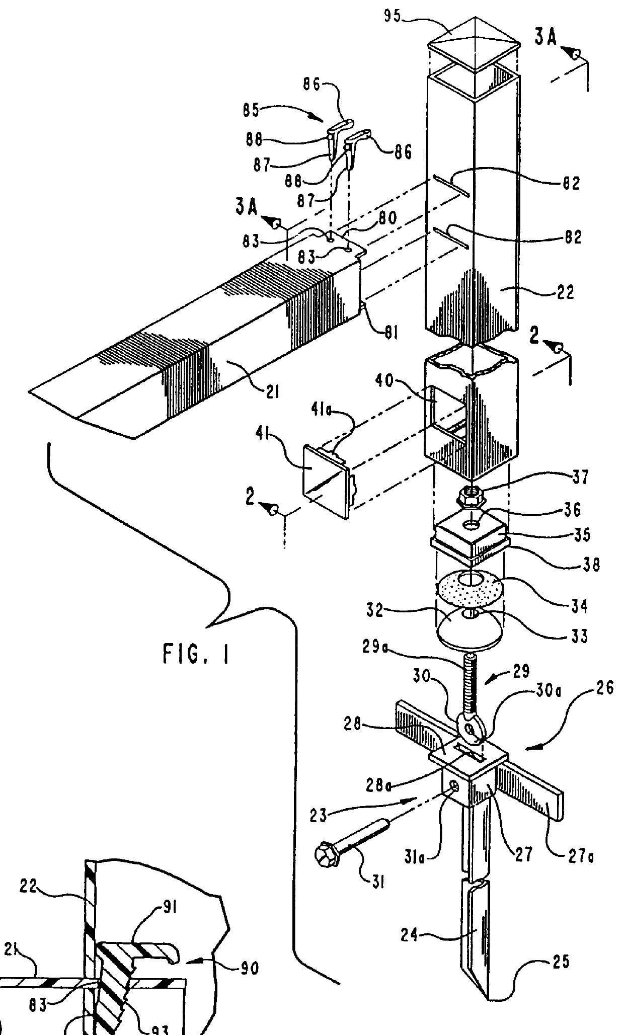
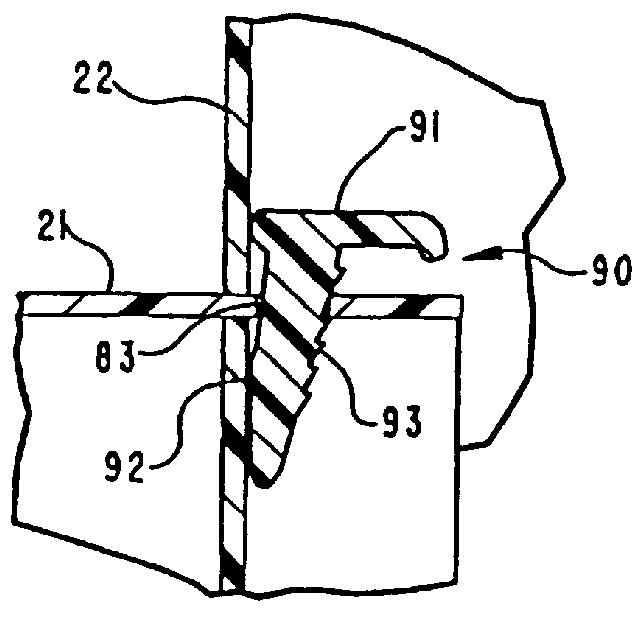
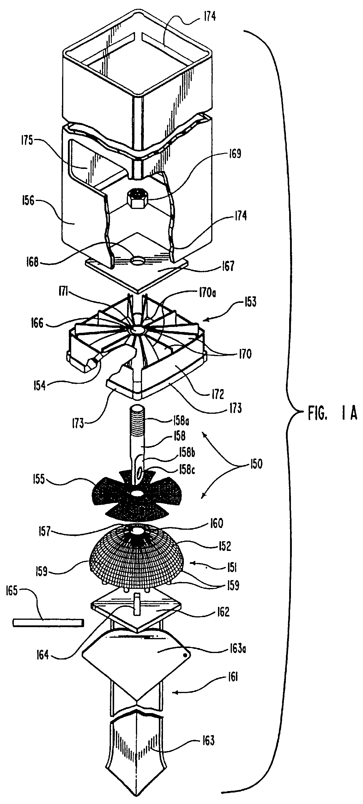
The present invention is in a post system that includes a number of novel and unique elements. FIG. 1 shows an exploded profile perspective view of one arrangement of post system 20, hereinafter referred to as system. In FIGS. 1 and 2, the system 20 is shown used for mounting a mail or newspaper tube 21, hereinafter referred to as tube, cantilevered out from the side of a post 22. Which post 22, its ground mounting arrangements and fastener components, as set out hereinbelow, are also useful for mounting a mail box as shown in FIGS. 10 through 12, and 17 through 19. Though, of course, the system 20 and the other embodiments therein could be utilized as a post alone, for example a fence post, or could be used for mounting any item, within the scope of this disclosure.

As thus shown in FIGS. 1 and 2 and as indicated by the descriptions herein, the post 22 is an outdoor-mountable post configured and adapted for supporting outdoor lateral loads such as loads imposed when the newspaper tu...


PUM


Abstract

An adjustable mounting for a post system for use in aligning and maintaining a post attached thereto to a desired vertical attitude to a ground surface. The adjustable mounting includes, as embodiments, a ball segment and seat combination that are movable with respect to one another, and in another embodiment involves a pair of interactive tapered washers, with the embodiments all including arrangements for clamping together the components that is a single bolt type fastener that is for maintaining the components of the adjustable mounting between a ground stake top surface, or ground surface, and a post bottom end or post insert base. The relative positioning of the seat to the ball segment and the tapered washers tapered surfaces to one another is to provide an off-set from a straight line axially through which adjustable mounting, that is transferred directly into a post, or a post insert with a post telescoped thereon, as an angle of that post to the vertical, which post can be used as a fences post, sign post, or the like, and may include an arrangement for mounting a container, such as a box or tube, cantilevered thereto that is intended for receiving delivered items, such as mail and / or newspapers.

Description

BACKGROUND OF THE INVENTION1. Field of the InventionThis invention related to adjustable post mountings and in particular to a post ground anchor that is capable of being tilted to bring the post to a desired vertical attitude.2. Prior ArtPosts and even ground mounting arrangements therefor for adjusting or tilting the post to a vertical attitude are not new. A recent patent to Deike, U.S. Pat. No. 4,603,520, shows an example of a mounting base for a sign post that will accommodate rotational, tilting and height adjustment. Where, like one embodiment the present invention, the Deike patent shows a ball and seat arrangement for providing tilting capability to a sign post, Deike utilizes four corner bolts to maintain that post tilted attitude rather than a ball and seat with a single bolt mounting like that of the present invention. Further, there is no teaching of a mail or newspaper box mounting to the mounting post in the Deike patent.Additionally, a number of ground anchor arrange...

Claims


Application Information

Patent Timeline
Patent Type & Authority Patents(United States)
IPC IPC(8): A47G29/00A47G29/12E01F9/018E01F9/011E04H12/22E04C3/30G09F7/18
CPCA47G29/1216E01F9/0112E01F9/0117E01F9/0188E04C3/30E04H12/2284G09F7/18H02B1/013E01F9/642E01F9/61E01F9/685
Inventor WEST, RONALD R.
Owner WEST RONALD R
Why Eureka
Try Eureka