
Mobile surface scrubber solution recovery system

Inactive Publication Date: 2000-02-15
ALTO U S
View PDF20 Cites 15 Cited by
  • Summary
  • Abstract
  • Description
  • Claims
  • Application Information

AI Technical Summary

Benefits of technology

Among the several objects and features of the present invention may be noted the provision of a scrubber having squeegees which retain substantially all cleaning solution and prevent a trail of cleaning solution when the scrubber turns; and the provision of a mobile surface scrubber having side squeegees which are unvaryingly oriented with respect to the scrubber frame to reduce manufacturing expense and risk maintenance.

Problems solved by technology

Although machines of this type work well when traveling forward in a straight line, cleaning solution may bypass the squeegees, leaving a trail of solution behind the machine, when the machine turns left or right.
However, these rear squeegee designs have not entirely overcome the problems associated with recovering cleaning solution during turns, because conventional rear squeegees do not pass over the entire wetted surface, even when they are arcuate and pivot.
However, because the motion of the machine during turns is not exactly perpendicular to the side squeegees, some of the cleaning solution flows parallel to the side squeegees and eventually flows past the ends of the squeegees so that streaks of cleaning solution trail behind the machines.
However, these linkages increase the complexity of the solution recovery system thereby increasing the cost and risk of failure.

Method used


Image

  • Mobile surface scrubber solution recovery system
  • Mobile surface scrubber solution recovery system
  • Mobile surface scrubber solution recovery system

Examples


Embodiment Construction

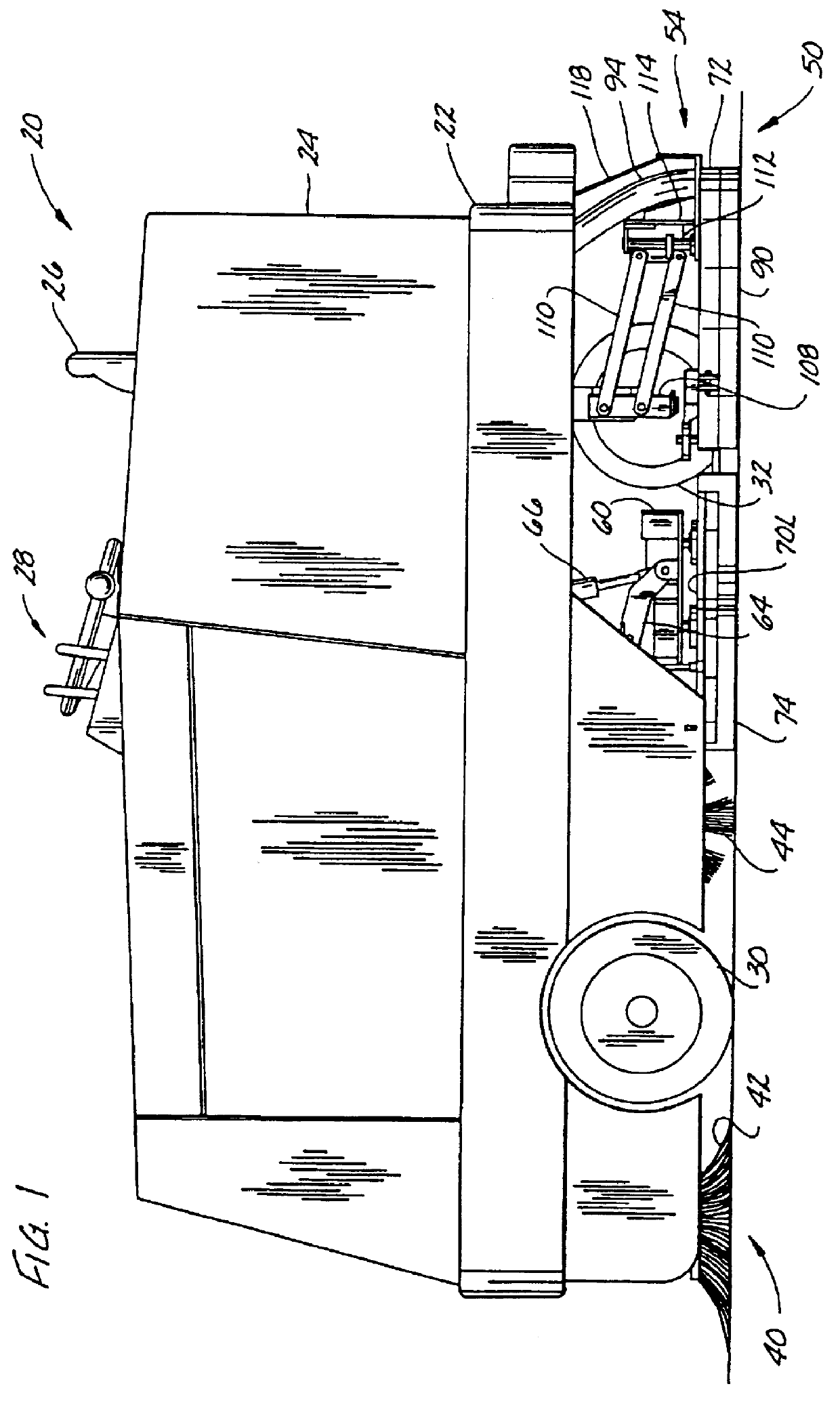
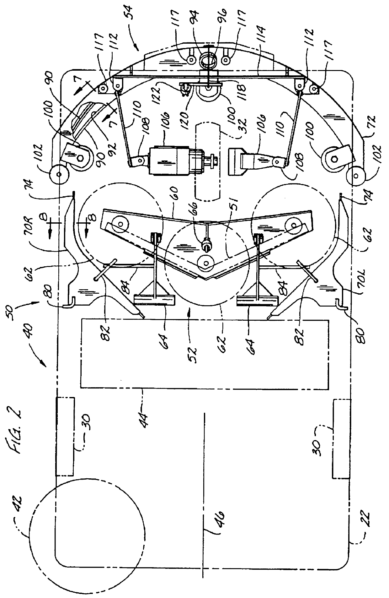
Referring now to the drawings and in particular to FIG. 1, a mobile surface scrubber indicated generally at 20 is of the type used to sweep and scrub a surface such as a warehouse or factory floor or a parking lot. The surface scrubber 20 has a frame 22 supporting a body 24 which houses the various sweeper and scrubber components. A seat 26 mounted on the body 24 permits an operator to ride on the scrubber 20. Hand operated controls, generally designated as 28, are positioned in front of the seat 24 so that the operator may access them when seated to control the scrubber 20 operation. Foot operated controls (not shown) are positioned on the floor in front of the seat 24. Two front wheels 30 and one rear wheel 32 are mounted on the frame 22. The rear wheel 32 is driven by an engine (not shown) such as a 2 liter, 45 hp. 4 cycle. Toyota gasoline powered engine, a 63 hp, gasoline or LP powered Ford engine, or a 46 hp, 4 cycle, Perkins diesel powered engine to propel the scrubber over th...


PUM


Abstract

A mobile surface scrubber for scrubbing a surface wetted with cleaning solution. The scrubber comprises a frame, a plurality of wheels rotatably mounted on the frame, scrub brush means attached to the frame and positioned to scrub the wetted surface as the scrubber is transported over the surface, and a recovery system for recovering cleaning solution from the surface. The recovery system includes a return tank for retaining recovered cleaning solution, a rear squeegee pivotally connected to the frame, and left and right side squeegees mounted on the frame. The rear squeegee is positionable to contact the surface behind the scrub brush means when the scrubber is transported in the forward direction. The side squeegees are unvaryingly oriented with respect to the frame and positionable to contact the surface on opposite sides of the scrub brush means. The rear squeegee is so constructed and operable that when the scrubber is transported in a right turning direction, the rear squeegee pivots relative to the frame to a position in which the right end of the rear squeegee overlaps the rearward end of the right side squeegee, and when the scrubber is transported in a left turning direction, the rear squeegee pivots relative to the frame to a position in which the left end of the rear squeegee overlaps the rearward end of the left side squeegee.

Description

BACKGROUND OF THE INVENTIONThis invention relates generally to a mobile surface scrubber for scrubbing a surface wetted with cleaning solution, and more particularly the invention relates to a solution recovery system for recovering cleaning solution from the wetted surface.Mobile surface scrubbers typically include a cleaning solution dispensing system, scrub brushes for scrubbing the wetted surface and one or more squeegees for removing used cleaning solution from the surface. The squeegees are frequently connected to a vacuum to improve the removal of the cleaning solution. In addition, scrubbers frequently include sweeper brushes to sweep debris from the surfaces, either concurrently with or independently from the surface scrubbing operation. The sweeper brushes are usually adapted to sweep the debris into a recovery bin. A vacuum is also frequently used to draw debris into the recovery bin.The scrubbers may be driven over a surface such as the floor of a factory or warehouse so...

Claims


Application Information

Patent Timeline
IPC IPC(8): A47L11/30A47L11/29F02B75/02
CPCA47L11/30A47L11/4011A47L11/4016A47L11/4038A47L11/4041A47L11/4044A47L11/4061A47L11/4072F02B2075/027
Inventor BURGOON, JACK L.LINE, DONALD E.
Owner ALTO U S
Features
  • Generate Ideas
  • Intellectual Property
  • Life Sciences
  • Materials
  • Tech Scout
  • Unparalleled Data Quality
  • Higher Quality Content
  • 60% Fewer Hallucinations
Learn More