
Self-countersinking screw with cutting receiving pockets

a self-countersinking screw and receiving pocket technology, which is applied in the direction of screws, threaded fasteners, fastening means, etc., can solve the problems of insufficient space, relatively difficult cutting edges, and insufficient upward diminishing volume of cutter recesses

Inactive Publication Date: 2000-06-20
ILLINOIS TOOL WORKS INC
View PDF18 Cites 20 Cited by
  • Summary
  • Abstract
  • Description
  • Claims
  • Application Information

AI Technical Summary

Benefits of technology

It is an object of the present invention to provide an improved self counter-sinking screw which would further advance the art by avoiding or at least reducing the above drawbacks.
Preferably, there is provided a tapered intermediate portion just under the underside of the head of the screw. Each recess preferably comprises a leading boundary which is convergent with said cutting edge in the direction along said underside and towards the axis of the screw. In accordance with another preferred feature of the invention, each said recess further comprises a flat upper boundary wall extending between upper ends of said trailing wall and said linear boundary in a circumferential direction and disposed near said top. The bottom of each recess is preferably planar and slopes such as to increase the depth of the recess in a direction toward the corner between the upper boundary wall and the trailing wall.

Problems solved by technology

It would be inoperative when the screw would have to be used with hard finish panels such as melamine, where the material cut from the panel cannot be removed toward the threaded portion of the screw.
However, since there is no provision for effective disposal of the burrs, the arrangement is only suitable in applications where the workpiece is from material such as wood composite material, but not with a hard, dense material.
This is disadvantageous from the standpoint, firstly, of the manufacturing costs as a curved edge is relatively difficult to produce.
Secondly, the upwards diminishing volume of the cutter recess does not provide sufficient space for the burrs from immediately adjacent areas of the workpiece as most of the material in self-countersinking is removed at the upper, larger diameter portion of the countersink.
Therefore, they take away more material than is required for countersinking the seat for the underside of the screw, which weakens the strength of the engagement between the head and the workpiece.

Method used


Image

  • Self-countersinking screw with cutting receiving pockets
  • Self-countersinking screw with cutting receiving pockets
  • Self-countersinking screw with cutting receiving pockets

Examples


Embodiment Construction

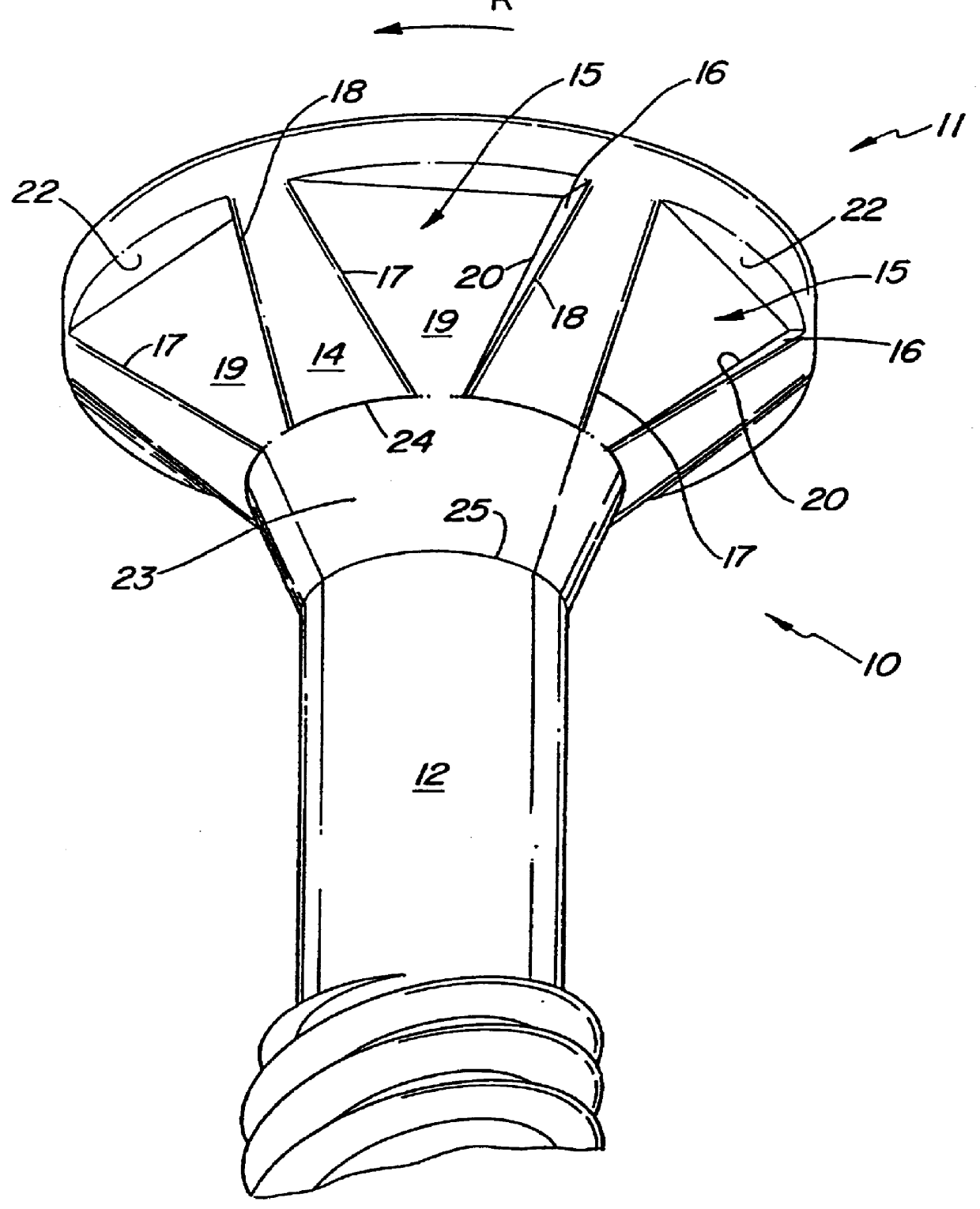
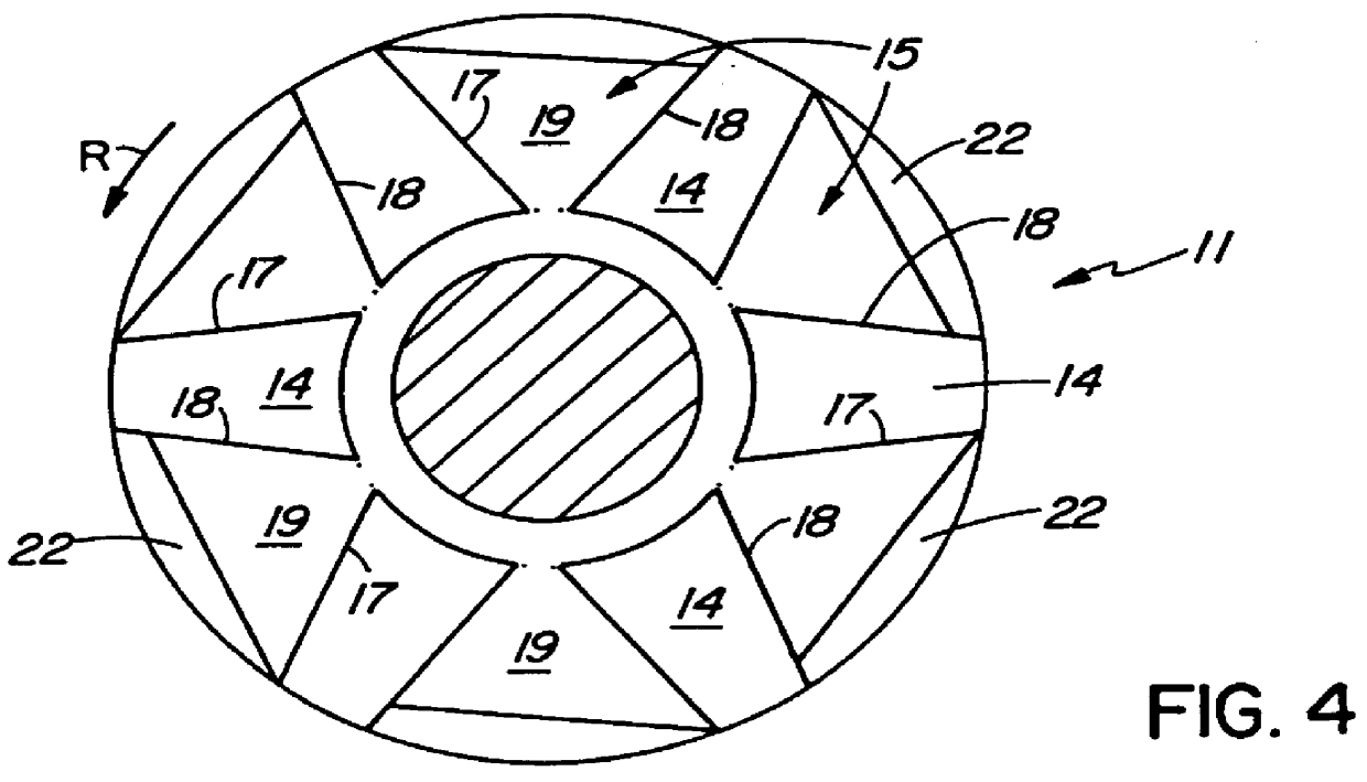
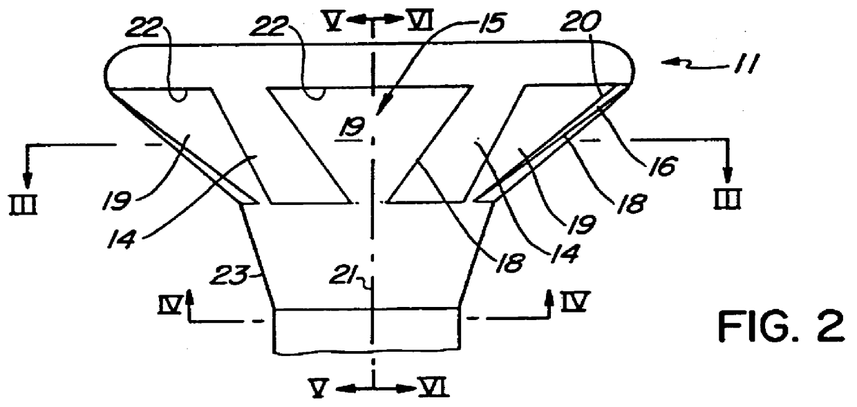
With reference to the drawings and in particular to FIGS. 1, 2 and 3 thereof, the self-countersinking screw 10 comprises a head 11 and a threaded stem portion 12. The head 11 has the general shape of an inverted-conical member and is formed; at the top, with screwdriver engaging means, in the embodiment shown, a hexagonal recess 13 adapted to receive the tip of a screwdriver (not shown). However, it should be noted that the screwdriver engaging means may be of any other suitable shape. The head exhibits an inversely frusto-conical underside 14 on which there are a plurality of generally triangular recesses 15.

The term "generally" triangular is used to indicate that the contour is not a true triangle as will be apparent from the description which follows. Each recess 15 comprises, from the standpoint of the direction of rotation R (FIGS. 1, 3, 4) driving the screw in a workpiece, a trailing wall 16 and a leading boundary 17. The trailing wall 16 forms a cutting edge 18 at the merger ...


PUM


Abstract

A self-countersinking screw including an inverted-conical head portion formed at a top with a cavity adapted to receive a tip of a screwdriver and having a conical bottom, said conical bottom having a plurality of triangular recesses each having a lateral side extending inwardly to form a sharp edge and a space for receiving chips, a threaded portion, and a tapered portion having a large diameter connected with the head portion and a small diameter connected with the threaded portion, whereby the sharp edge will make a countersink on a workpiece when the countersunk head screw is turned therein.

Description

Matter enclosed in square brackets .[. .]. appears in the original patent but forms no part of this reissue specification; matter printed with underlining indicates the additions made by reissue.BACKGROUND OF THE INVENTIONThe invention relates to a self-counter sinking screw. Different kinds of self counter-sinking screw are know from prior art.It is known, e.g. from U.S. Pat. No. 5,203,657 (Nagoshi et al.) to provide a self-tapping screw, where the generally conical undersurface of the head of the screw is particularly configured to prevent the bulging up of a gypsum board cover sheet. In one embodiment, the underside of the head is provided with a series of equidistantly spaced apart spot facing projection which also provide the burring action to make space for the inversely conical underside of the head. This arrangement may be useful with gypsum board panels or the like material, where the material of the board is soft, has a relatively small density and is easily displaceable o...

Claims


Application Information

Patent Timeline
Patent Type & Authority Patents(United States)
IPC IPC(8): F16B35/06F16B35/04
CPCF16B35/065F16B35/06
Inventor WALTHER, ULIYU, CHAO-HSIN MICHAEL
Owner ILLINOIS TOOL WORKS INC
Learn More