Video signal coding method

a video signal and signal coding technology, applied in the field of video signal coding methods, can solve the problems of objectionable poor quality of pictures reproduced discontinuous contents of pictures generated by interpolation at the receiver, and objectionable poor quality of pictures reproduced with such motion vectors

Inactive Publication Date: 2000-12-26
SONY CORP
View PDF15 Cites 8 Cited by
  • Summary
  • Abstract
  • Description
  • Claims
  • Application Information

AI Technical Summary

Problems solved by technology

In practice, however, it is not always possible for the transmission apparatus to generate accurate motion vector information in the frame skipping process, and in the event that inaccurate motion vectors are transmitted in this fashion, the pictures reproduced by interpolation at the receiver can be objection...

Method used


Image

  • Video signal coding method
  • Video signal coding method
  • Video signal coding method

Examples


Embodiment Construction

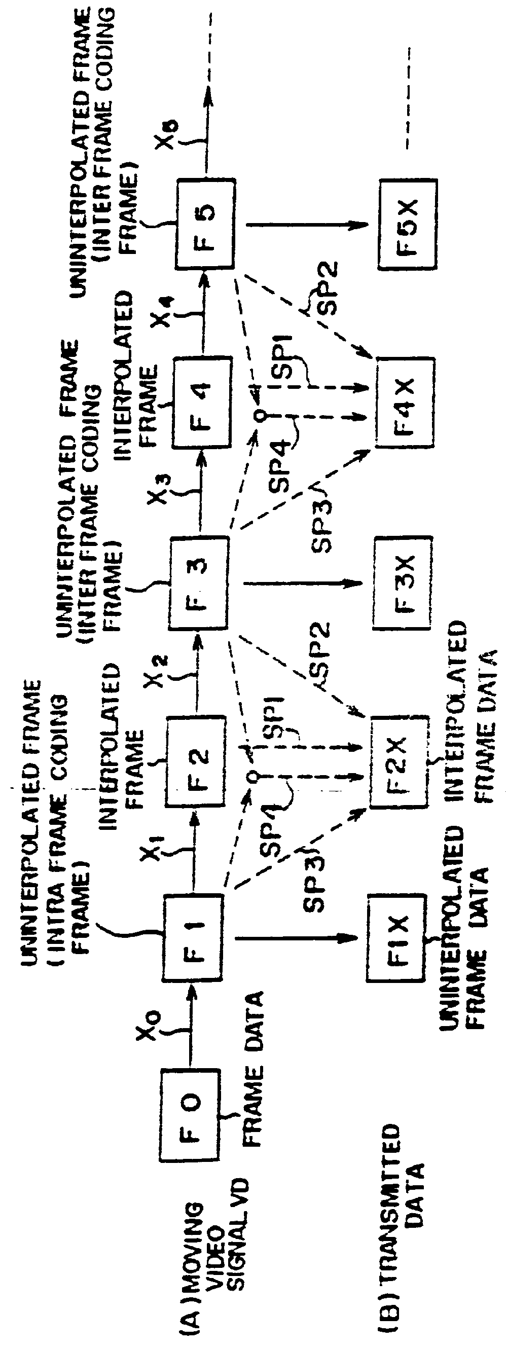
With reference first to FIG. 1, a video signal coding method in accordance with one embodiment of the present invention is illustrated therein as a method of operating a moving picture signal transmission system. In the illustrated method, picture data in the form of successive frames including frames formed by interpolation are produced by a transmitter and transmitted thereby to a receiver.

As shown in line (A) of FIG. 1, a moving video signal VD to be encoded for transmission includes successive frames of data comprising an initial frame F0 and successively arranged frames F1, F2, F3, . . . . Motion vectors x.sub.0, x.sub.1, x.sub.2, x.sub.3, etc., represent motion respectively between the frames F0 and F1, F1 and F2, F2 and F3, F3 and F4, etc. The transmitter applies an interpolation process to the even numbered frames F2, F4, . . . , to thereby generate respective interpolated frame data F2X, F4X, etc. as illustrated in line (B) of FIG. 1 and transmits the interpolated frame dat...


PUM


Abstract

In a method for encoding successive frames of a digital motion video signal in the form of compressed digital data including an intraframe coded signal and a plurality of interframe coded signals, a first frame of the digital motion video signal is encoded to form one of an intraframe coded signal and an interframe coded signal to produce a compressed digital signal; the compressed digital signal is decoded to form a decoded signal; a plurality of predicted video signal frames are produced representing a second frame of the digital motion video signal other than the first frame, at least one of the plurality of predicted video signal frames being produced with the use of the decoded signal and a motion vector representing motion between frames of the digital motion video signal; the plurality of predicted video signal frames are compared with the second frame of the digital motion video signal for producing a plurality of difference data each corresponding with a respective one of the plurality of predicted video signal frames; one of the predicted signal frames having a smallest corresponding difference data is selected; and an interframe coded signal of the compressed digital data corresponding to the selected one of the predicted video signal frames is generated.

Description

BACKGROUND OF THE INVENTIONThe present invention relates to video signal coding methods and, more particularly relates to such methods which are suitable for use in transmitting a moving picture video signal.Conventionally, in a moving picture video signal communication system, such as a conference system for a video telephone system, a moving picture video signal is transmitted to a remote point via a transmission line. It has been proposed to efficiently utilize the limited capacity of the transmission line by transmitting less than all of the successive frames of the signal according to a so-called frame skipping process. The receiver reproduces the frames that have been skipped by the transmitter by interpolation based on picture information for the frames preceding and following the skipped frames with the use of motion vectors transmitted in place of the skipped frames (refer to Japanese Patent Publication No. 60-28392).Since the motion vectors include less information than co...

Claims


Application Information

Patent Timeline
IPC IPC(8): G06T9/00H04N7/46H04N19/50H04N19/107H04N19/126H04N19/137H04N19/139H04N19/149H04N19/154H04N19/176H04N19/196H04N19/423H04N19/46H04N19/503H04N19/51H04N19/577H04N19/59H04N19/593H04N19/61H04N19/625H04N19/70H04N19/80H04N19/85H04N19/91H04N19/93
CPCH04N19/00H04N19/51H04N19/577H04N19/587H04N19/59H04N19/61
Inventor YONEMITSU, JUNANDREWS, BARRY D.
Owner SONY CORP
Why Eureka
Try Eureka