
Detection of progressive central hypovolemia

a technology of progressive central hypovolemia and blood volume, which is applied in the field of system for detection of abnormal decrease in blood volume, can solve the problems of continued re-calibration, disruption of signal, and limited commercially viable time-domain analysis approaches of arterial pulses, and achieves less complexity, less problems and disadvantages, and the effect of avoiding problems

Active Publication Date: 2015-05-28
EMPIRICAL TECH CORP
View PDF1 Cites 5 Cited by
  • Summary
  • Abstract
  • Description
  • Claims
  • Application Information

AI Technical Summary

Benefits of technology

The present invention provides a way to measure blood pressure at a single site with greater accuracy and at a lower cost compared to multiple-site measurements. It does not require a sensor to directly couple to the artery to obtain the blood pressure reading, making it more comfortable for the wearer. The approach uses a time-based analysis of the pulse waves to determine the blood pressure based on the time it takes for the pulse waves to travel through the arterial system. This approach is less dependent on the coupling pressure to the artery, increasing comfort for the wearer, and it avoids the need for constant re-calibration after motion has occurred. The invention also uses a physiological model of the arterial pulse to analyze the individual pulses and detect any changes in blood pressure. Overall, the invention improves the accuracy and comfort of blood pressure monitoring.

Problems solved by technology

In the absence of a comprehensive physical understanding of the structure of the pulse in the arterial periphery it is therefore not surprising that commercially viable time-domain analysis approaches of the arterial pulse have so far limited themselves to the determination of arterial pulse propagation velocities alone.
In addition, by using algorithms that are based on a physiological model of the arterial pulse, the approach is neither subject to continued re-calibrations after motion has occurred, nor otherwise induced disruptions of the signal.
The goal has been somewhat elusive up until now because of the uncertainty of determining physiologically relevant arterial pulse markers.

Method used


Image

  • Detection of progressive central hypovolemia
  • Detection of progressive central hypovolemia
  • Detection of progressive central hypovolemia

Examples


Embodiment Construction

Definitions

[0032]Where the definition of terms departs from the commonly used meaning of the term, applicant intends to utilize the definitions provided below, unless specifically indicated. For the purposes of the present invention, the term “plethysmograph” refers to an instrument that measures variations in the size of an organ or body part on the basis of the amount of blood passing through or present in the part.

[0033]For the purposes of the present invention, the term “horse race” refers to a contest of speed among horses that either are ridden by jockeys or pull sulkies and their drivers.

[0034]For the purposes of the present invention, the term “substantial” refers to an ample or considerable amount, quantity or size. Accordingly, the term “substantially comparable” as employed herein refers to data or information that can enables a diagnosis to be made based on a comparison of the patient's real time data to the substantially comparable data.

[0035]For the purposes of the pre...


PUM


Abstract

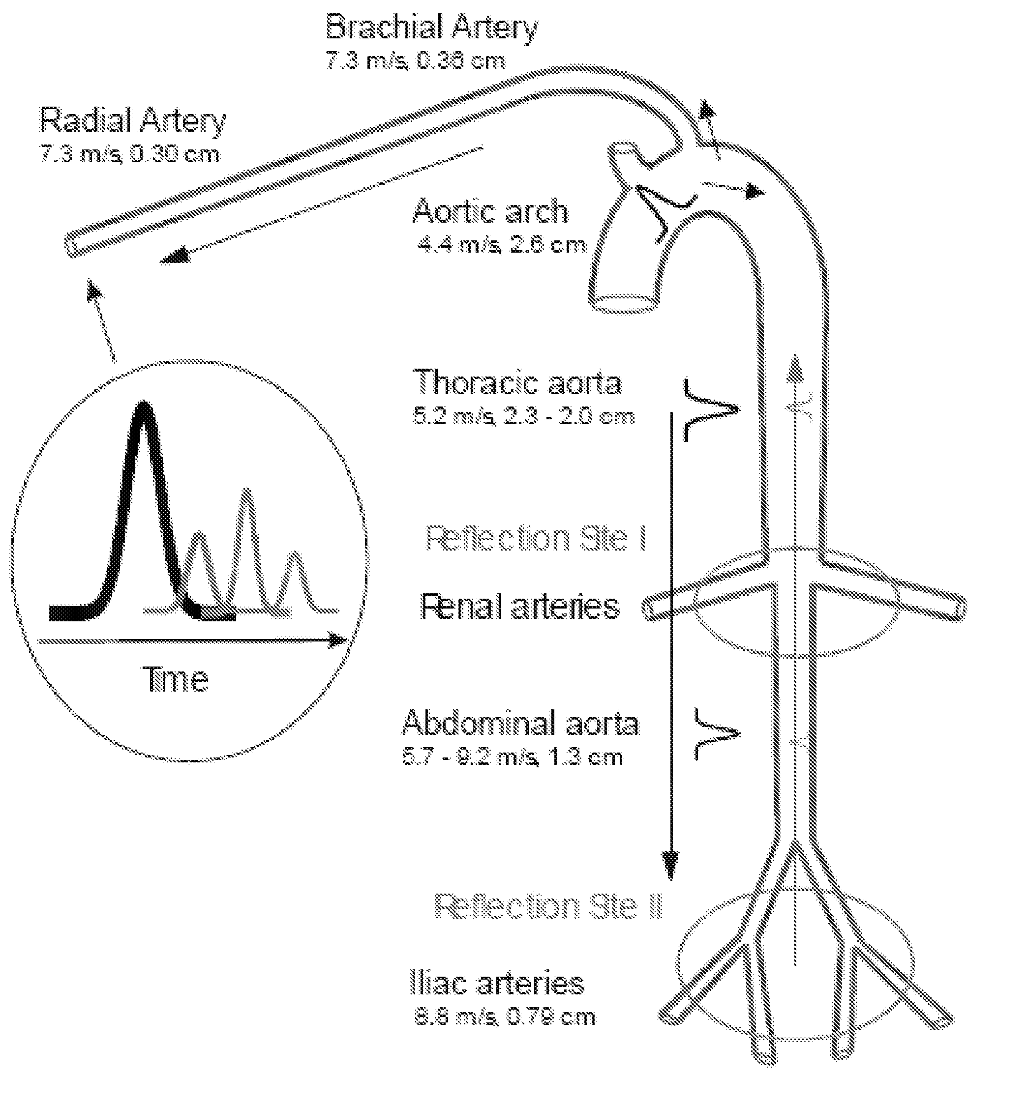
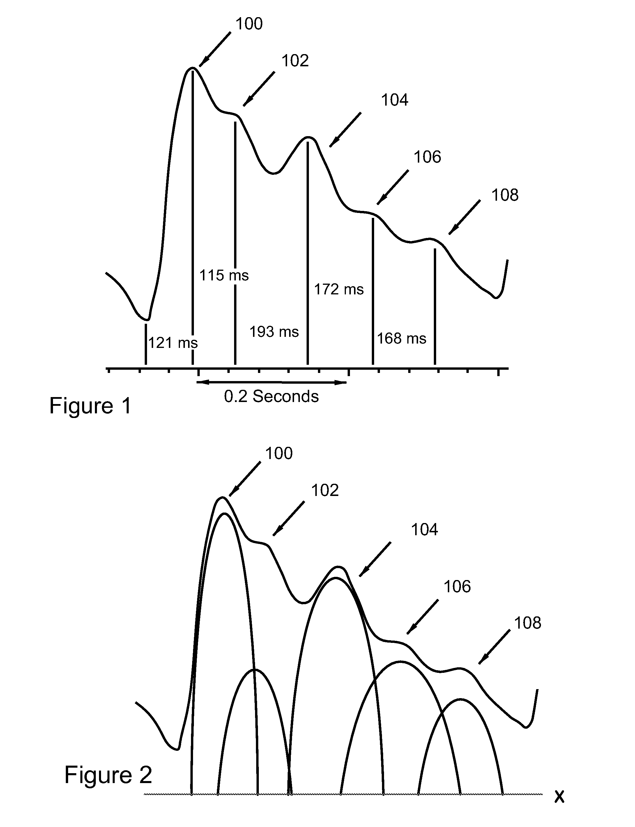
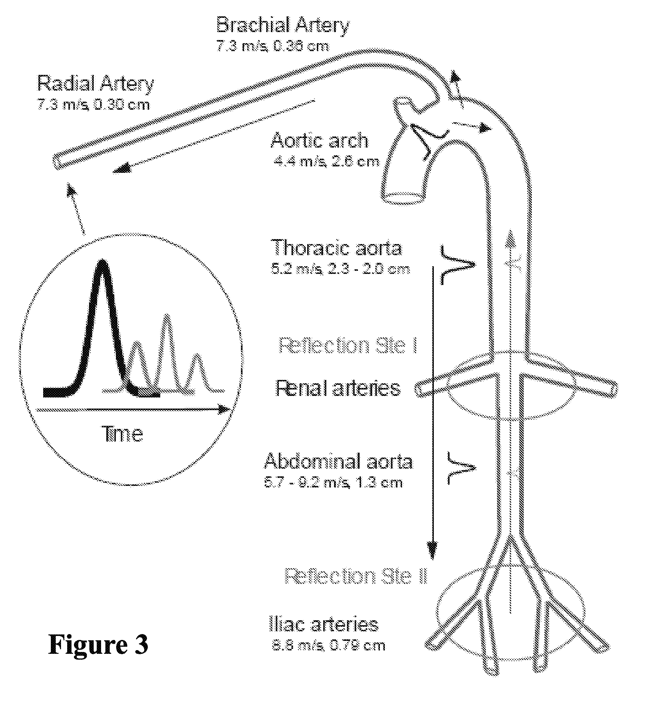
A system for detecting dehydration, hemorrhaging, and increases in blood volume comprising monitors the time difference between the arrival of the primary left ventricular ejection pulse (pulse T1) and the arrival of the iliac reflection (pulse T3) to determine an arterial pulse parameter which is the time difference between T1 T3. Changes in T3 minus T1 are indicative of something happening to blood volume. If the T1-3 value goes up and the patient is on an infusion system, it can be an indication of having too much fluid pumped and if T1-3 is lower than it should be for an individual, they are either dehydrated (which can result in decreases in blood volume), they are hemorrhaging, or they have hemorrhaged. A downtrend in T13 can tell whether someone is continuing to hemorrhage

Description

CROSS-REFERENCE TO RELATED APPLICATION[0001]This application is a continuation-in-part of co-pending US patent applications, Ser. No. 13 / 231,703 filed Sep. 13, 2011 for Hydrostatic Finger Cuff Blood Wave Form Analysis; Ser. No. 12 / 854,954 for Hydrostatic Finger Cuff Blood Wave Form Analysis filed Aug. 12, 2010; Blood Pressure Determination Based on Delay Times between Points on a Heartbeat Pulse, pending patent application, U.S. patent Ser. No. 12 / 537,228 filed Aug. 6, 2009; Method for Arterial Pulse Decomposition Analysis for vital Signs Determination, pending patent: Ser. No. 11 / 500,558 filed Aug. 8, 2006, which is a C-I-P of U.S. Pat. No. 7,087,025 for Blood Pressure Determination Based on Delay Times Between Points on a Heartbeat Pulse issued Aug. 8, 2006, and Wrist Plethysmograph, Ser. No. 11 / 803,643 filed May 15, 2007, and Apparatus and Method for Measuring Pulse Transit Time, U.S. Pat. No. 6,723,054 issued Feb. 26, 2001, which is a divisional of Ser. No. 09 / 763,657, all of wh...

Claims


Application Information

Patent Timeline
IPC IPC(8): A61B5/02A61B5/00A61B5/021
CPCA61B5/02042A61B5/7278A61B5/02125A61B5/7275G16H40/63G16H50/50G16H50/20G16H20/40Y02A90/10G16H50/30
Inventor BARUCH, MARTINGERDT, DAVIDADKINS, CHARLES
Owner EMPIRICAL TECH CORP
Learn More