
Compact fluorescent luminaire

a fluorescent luminaire and compact technology, applied in the field of compact fluorescent luminaires, can solve the problem that the attempt to utilize this method of achieving a greater light output density is inherently constrained

Inactive Publication Date: 2001-08-07
SYLVAN R SHEMITZ DESIGNS INC
View PDF11 Cites 6 Cited by
  • Summary
  • Abstract
  • Description
  • Claims
  • Application Information

AI Technical Summary

Benefits of technology

It is an object of this invention to provide an arrangement for orienting multiple elongated lamps in a lighting fixture that allows the placement of the multiple lamps closer together than would normally be allowed by the size of the lampholders.
It is also an object of this invention to provide an arrangement for orienting multiple elongated lamps in a lighting fixture that allows the placement of the multiple lamps such that they are tightly gathered to simulate a hairline source of light, and in particular a hairline source of light centered on the focus or optical center of the reflector.
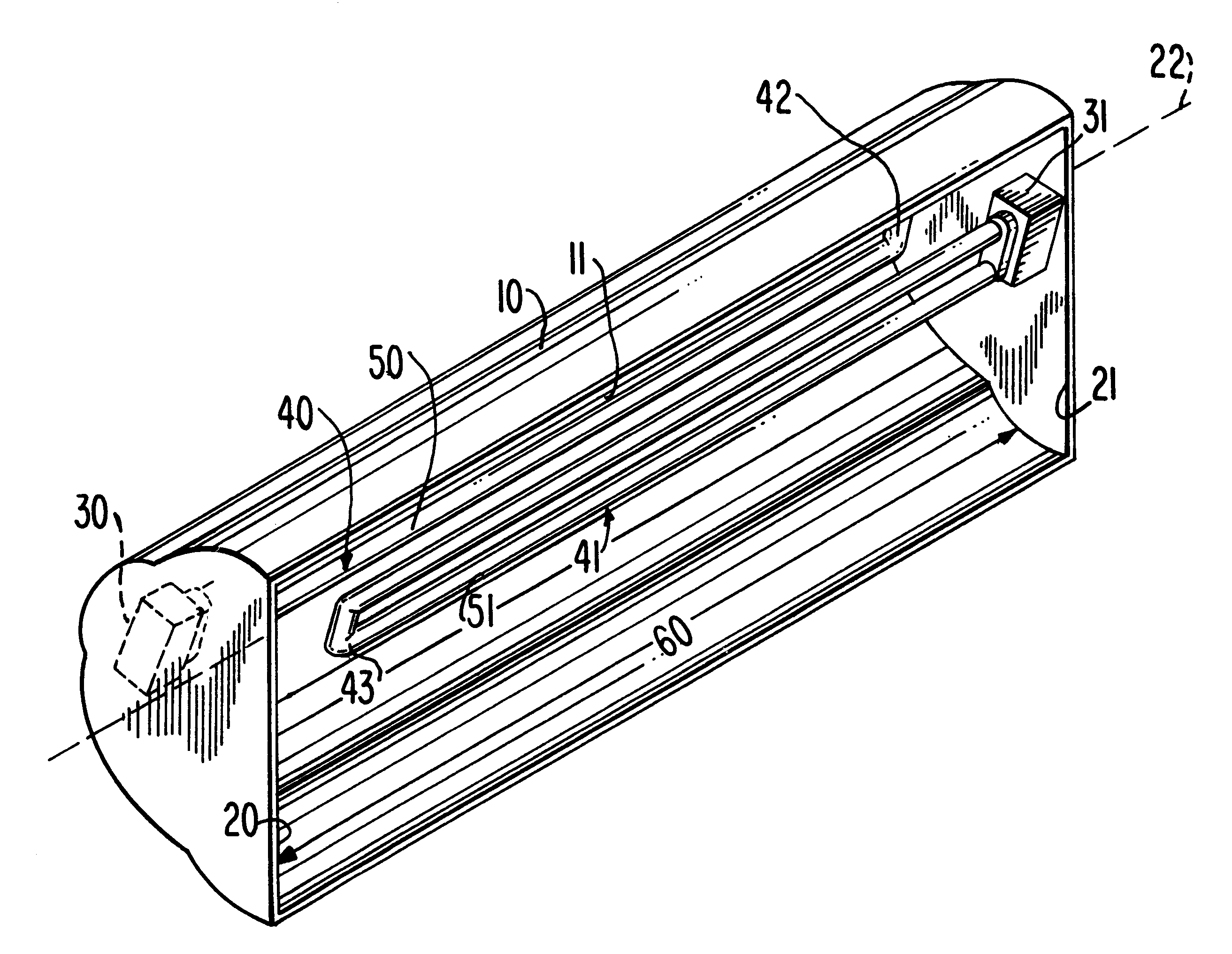
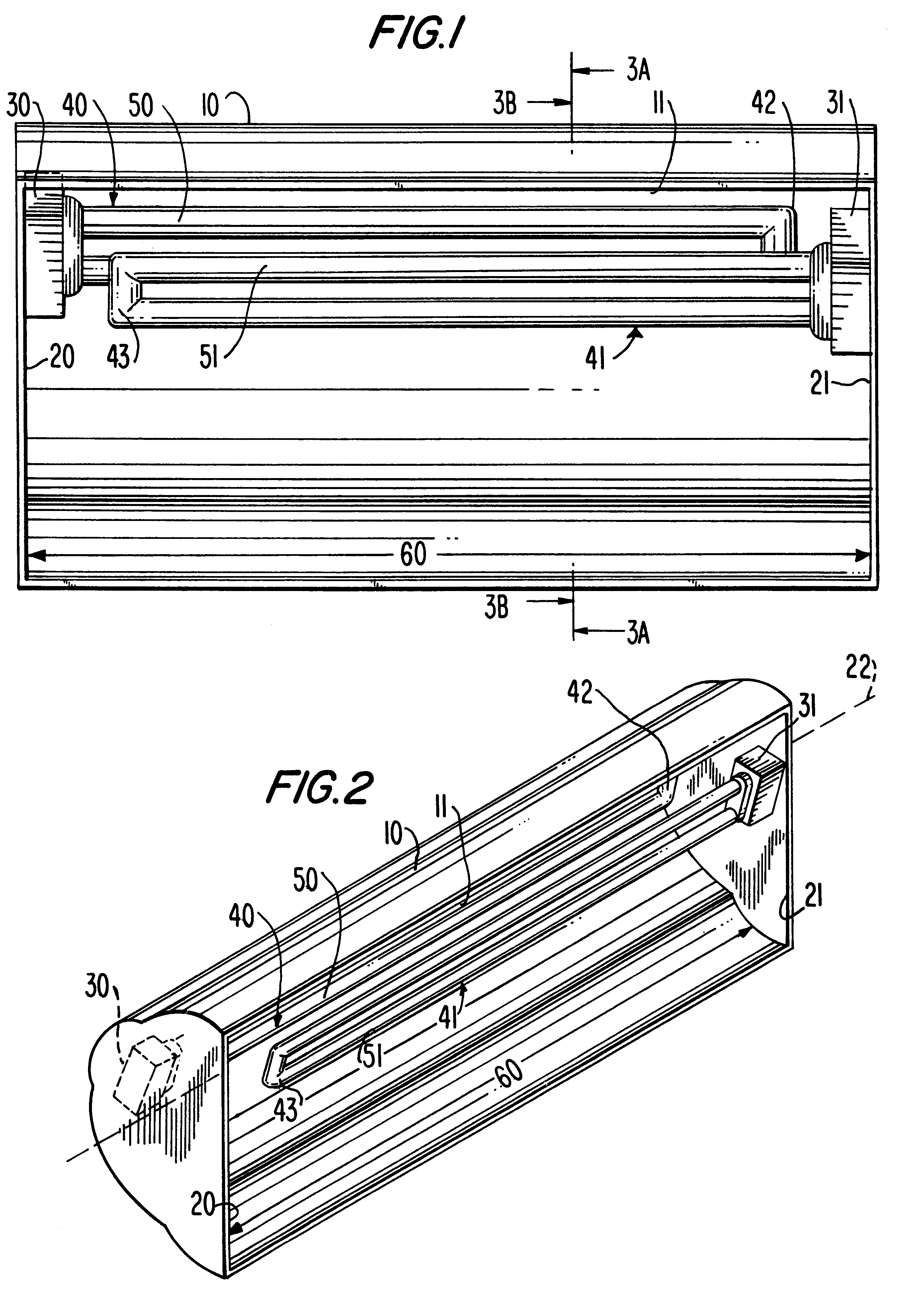
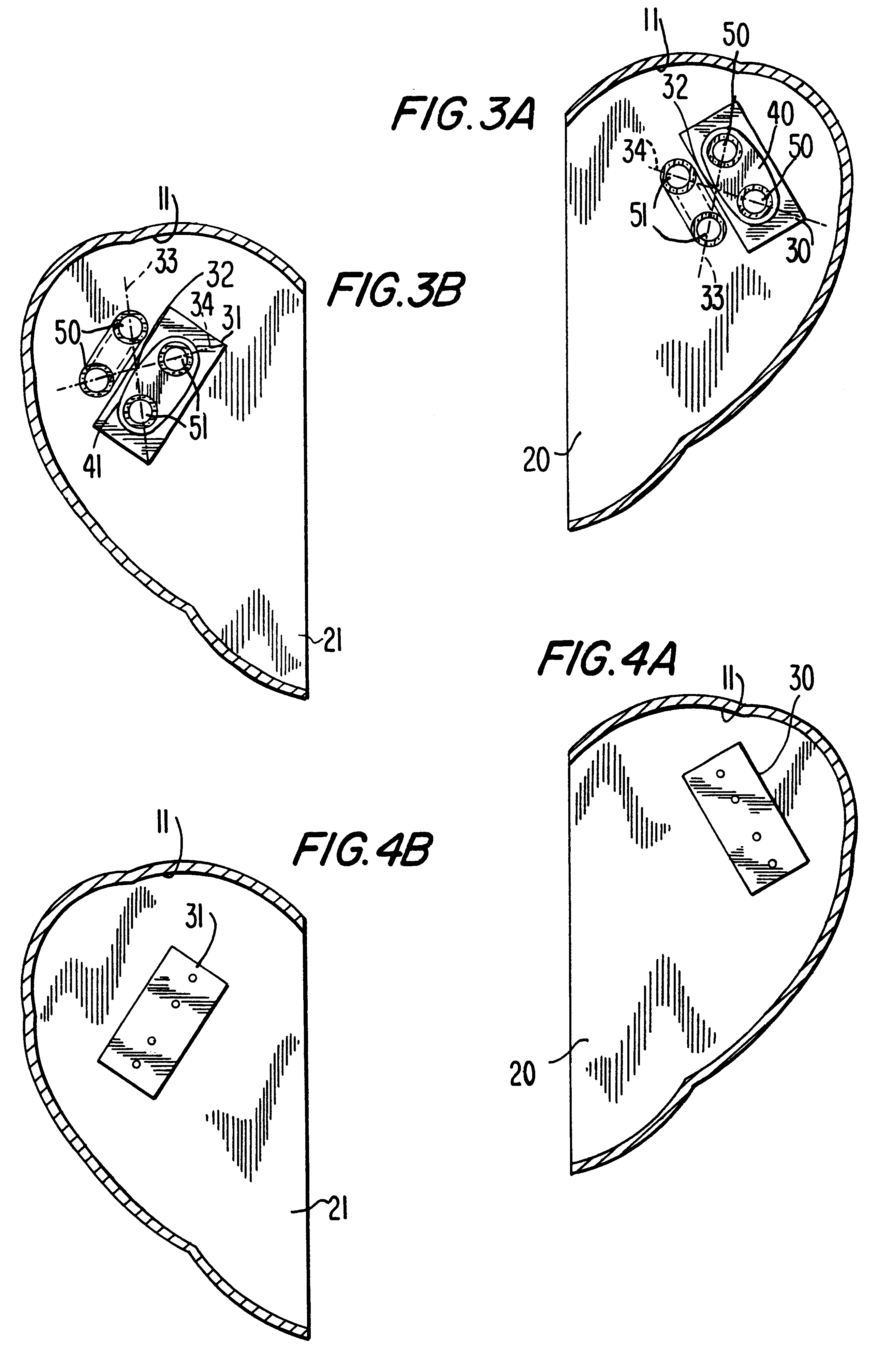
In accordance with this invention, there is provided a lighting fixture for producing enhanced lamp light output density. The fixture includes a reflector having two ends, a fixture optical centerline extending between the ends, and a fixture length along the fixture optical centerline. At least one lampholder is mounted substantially adjacent each of the ends of the reflector, each lampholder being mounted at its respective location such that a projection of each lampholder along the fixture optical centerline toward the other lampholder partially overlaps the other lampholder. Each lampholder has a lampholder length. The fixture further includes at least two elongated lamps, each lamp having a plug portion for mating with one of the lampholders, the plug portion having a plug portion length, a distal portion opposite the plug portion, a lamp longitudinal axis running from the plug portion to the distal portion, and a lamp length along the lamp longitudinal axis from the plug portion to the distal portion. Each of the lamps is mounted in one of the lampholders such that the lamp longitudinal axes of the lamps are substantially parallel to the optical centerline and are offset from one another. A portion of the plug portion remains exposed when the lamp is mounted in the lampholder. The exposed portion has an exposed plug portion length. The fixture length is sufficiently greater than the sum of: (1) the lamp length of one of said lamps, (2) the exposed plug portion length of that one of the lamps, (3) the lampholder length of one of the lampholders associated with that one of the lamps, (4) the exposed plug portion length of the plug portion of another of the lamps, and (5) the lampholder length of the lampholder associated with the other of the lamps, that for adjacent lamps, being associated with lampholders mounted adjacent different ends of the reflector, the distal portion of any one of the lamps longitudinally clears the lampholder associated with, and the exposed plug portion of, any of the lamps adjacent that one of the lamps; and the lamps together form a lamp optical centerline substantially coincident with the fixture optical centerline.

Problems solved by technology

However, attempts to utilize this manner of achieving a greater light output density are inherently constrained by the dimensions of lampholders.

Method used


Image

  • Compact fluorescent luminaire
  • Compact fluorescent luminaire
  • Compact fluorescent luminaire

Examples


Embodiment Construction

The present invention provides an arrangement for lighting fixtures that produces a greater lamp light output density--i.e., more luminous flux (measured in lumens) from a smaller, more compact array of lamps--than could otherwise be obtained. This is achieved by mounting the lampholders for adjacent lamps on opposite sideplates of the lighting fixture and by increasing the inside dimension of the lighting fixture enough to accommodate the presence of lampholders at both ends. In this way, the lampholder for each lamp does not interfere with any portion of any adjacent lamp and the lampholders are no longer a limiting factor in how close the lamps can be to one another. The lamps can therefore be mounted close enough together so that they are tightly gathered and simulate a hairline source having an effective optical centerline substantially coincident with the optical centerline, or focus, of the reflector of the lighting fixture.

A preferred embodiment of a lighting fixture designe...


PUM


Abstract

An arrangement for two side-by-side elongated lamps in a lighting fixture in which lampholders are alternately mounted on opposite sideplates or brackets of the lighting fixture. The lighting fixture has an inside dimension that is longer than the length of each lamp / lampholder combination by a length sufficient to prevent the distal end of each lamp from overlapping the exposed plug portion and the lampholder of any of the adjacent lamps. The lamps are tightly gathered, and are close enough together to simulate a hairline light source having an optical centerline coincident with the optical centerline of the fixture.

Description

BACKGROUND OF THE INVENTIONThis invention relates to lighting fixtures. More particularly, this invention relates to lighting fixtures utilizing two elongated lamps to produce increased lamp light output density.One goal of the lighting industry has been to provide luminaires--lighting fixtures with lamps--with ever higher lamp light output densities. Light output density is generally measured in lumens / foot (L / F), a lumen being a unit of luminous flux. For example, a two-foot-long (approximately 0.61-meter--long) lamp that produces 1000 lumens achieves 500 L / F (approximately 1,639 L / Meter).One manner of providing a higher lamp light output density has been to use high output lamps, which achieve a greater luminous flux (measured in lumens) from the same size lamp. For example, while a typical four-foot-long (approximately 1.22-meter-long), 32 -watt, T8-size, rapid start lamp will produce a luminous flux of 2,950 lumens, for 737 L / F (approximately 2,418 L / M), a typical four-foot-lon...

Claims


Application Information

Patent Timeline
Patent Type & Authority Patents(United States)
IPC IPC(8): F21V7/00
CPCF21V7/005F21Y2113/00F21Y2103/37
Inventor SHEMITZ, SYLVAN R.
Owner SYLVAN R SHEMITZ DESIGNS INC
Learn More