
Electrode structure for measuring electrical responses from the human body

a technology of electrical responses and electrodes, applied in electromyography, medical science, sensors, etc., can solve the problems of reducing the accuracy of measurement, interfering signals, and not always achieving satisfactory results, so as to reduce the creation of eddy currents

Inactive Publication Date: 2008-10-21
NEXSTIM
View PDF16 Cites 31 Cited by
  • Summary
  • Abstract
  • Description
  • Claims
  • Application Information

AI Technical Summary

Benefits of technology

[0013]The solution according to the invention permits electrical responses to be measured during, or a short time after the magnetic pulses produced by the magnetic stimulators, typically after 1-5 ms, even after a powerful magnetic pulse, particularly if the solution according to the invention is used in conjunction with magnetic stimulation simultaneously with suitable EEG equipment.
[0014]The electrode structure according to the invention forms a stable electrical contact between the person being measured and the electrode. The attachment construction of the electrode is compact in size, thus permitting a TMS coil to be placed close to the surface of the head. The coil's effective distance is about 30 mm and the effective electrical field induced diminishes rapidly as the distance increases. The solution according to the invention permits the coil to be placed closer to the point it is wished to affect. With the aid of the invention, it is possible to create in the brain a TMS-induced electrical field that is typically 5-30% stronger than when using thicker electrode attachment constructions. The value of a 5-30% stronger electrical field is calculated from a distance difference of 2-3 mm, i.e. if the electrode's attachment were to be 2-3 mm thicker, the electrical field induced by TMS in the tissue would be correspondingly weakened.
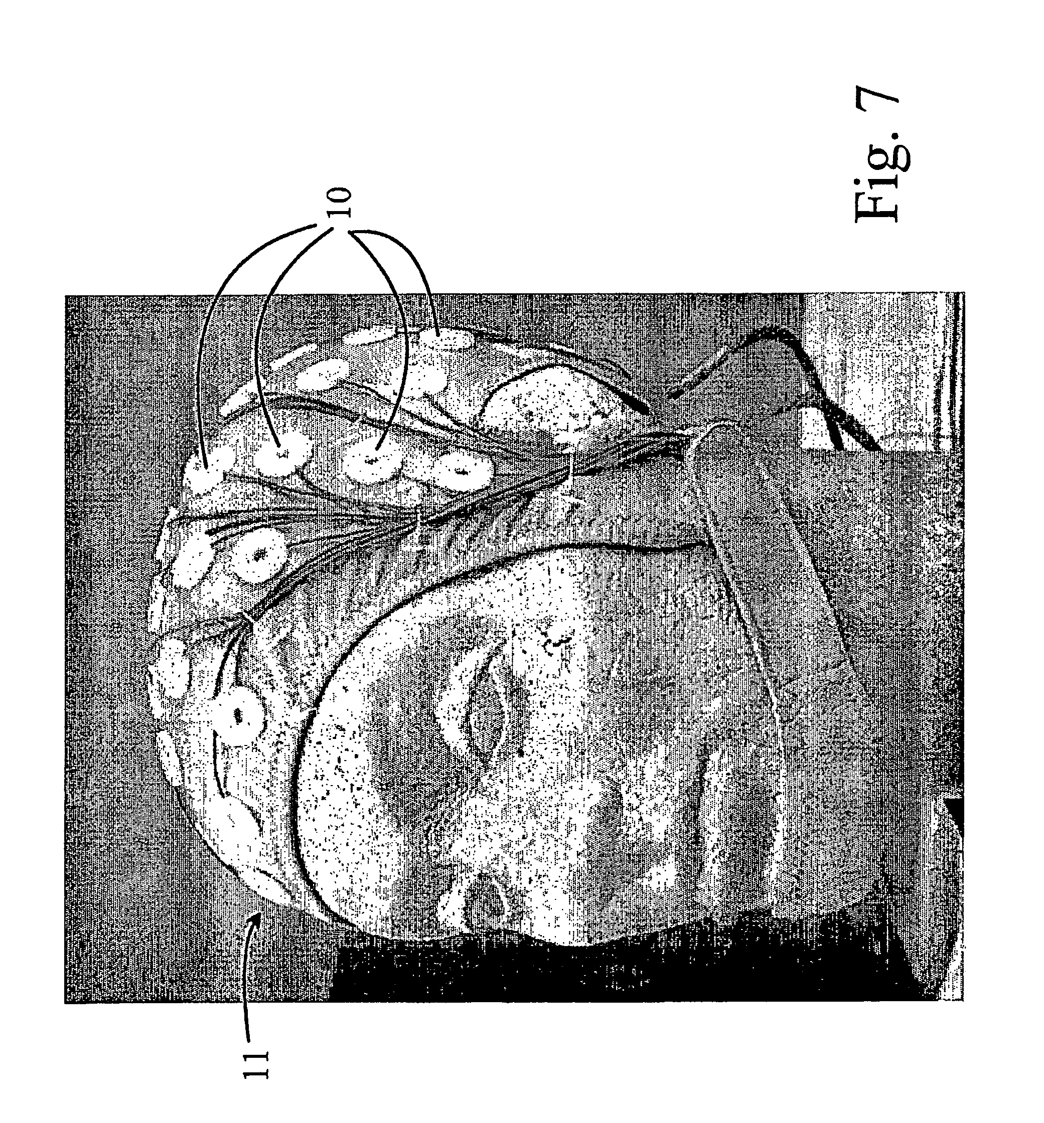
[0015]According to one preferred alternative of the invention, the electrode structure 10 is entirely non-magnetic, i.e. the magnetization of all the structural materials is very small. For example, this is a great advantage and even an essential requirement in measurements made in connection with an MEG (magnetoencephalography) device. MEG compatibility is, in turn, a great advantage in laboratories and in applications, in which TMS and EEG, as well as MEG measurements are used. A non-magnetic structure is also very important if EEG measurements are made during MRI imaging (Magnetic Resonance Imaging), for example, in connection with FMRI (Functional Magnetic Resonance Imaging) tests. The electrode structure (10) is constructed in such a way that a special tool is needed to detach it, while, in addition, the construction protects the brittle silver-chloride electrode (1) from impacts, scratching, and wear.
[0017]In addition, the measurement point on the skin of the test person can be cleaned after the attachment of the electrode, as there is a sufficiently large hole (6) in the electrode structure.
[0018]The small size and compact shape of the electrode prevents the magnetic stimulation coil from inducing strong electromotor forces in the electrode and thus reduces the creation of eddy currents caused by the electrical fields.

Problems solved by technology

In practice, electrically polarizing interfaces arise between the different materials in the silver electrodes according to the prior art and lead to interference signals that diminish the accuracy of the measurement.
Despite this measure, satisfactory results are not always achieved.
As chloridization only affects the surface of the electrode, it is easily removed by wear or, for example, by unintentionally scratching the electrode.
Chloridization must be performed regularly between measurements, leading to additional work and preventing continuous use of the electrodes.
In measurement caps according to the prior art, the electrode structures become detached easily during washing and are difficult to reattach.

Method used


Image

  • Electrode structure for measuring electrical responses from the human body
  • Electrode structure for measuring electrical responses from the human body
  • Electrode structure for measuring electrical responses from the human body

Examples


Embodiment Construction

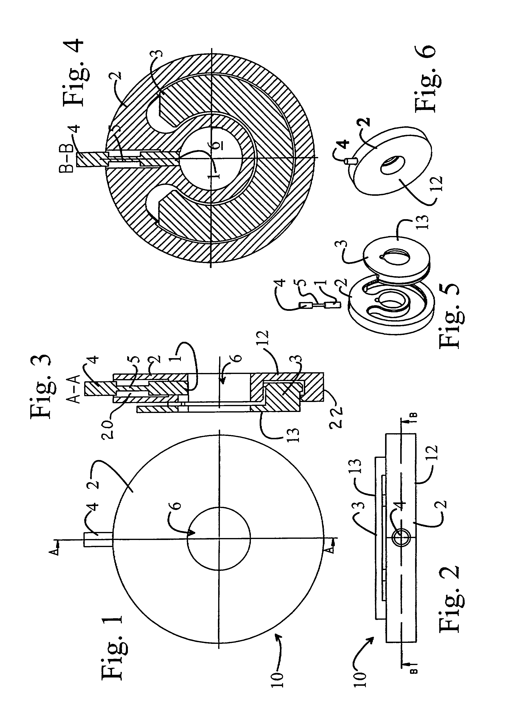
[0027]According to FIG. 1, the electrode structure according to the invention is examined from beneath, in other words, from the direction of the measurement subject. The electrode structure 10 includes a body piece 2, from which a measuring lead 4 protrudes. Electrical contact from the measurement subject, typically a person's scalp, to the electrode material, is formed through the hole 6, with the aid of an electrically conductive paste. According to the figure, the electrode structure 10 is essentially disc-shaped.

[0028]FIG. 2 shows the locking piece 3 connected to the body piece, by means of which the measuring cap described later is locked between the body piece and the locking piece. The locking piece 3 is located on the outer surface of the electrode structure, if the inner surface 12 is defined as the measuring surface, for example, the scalp.

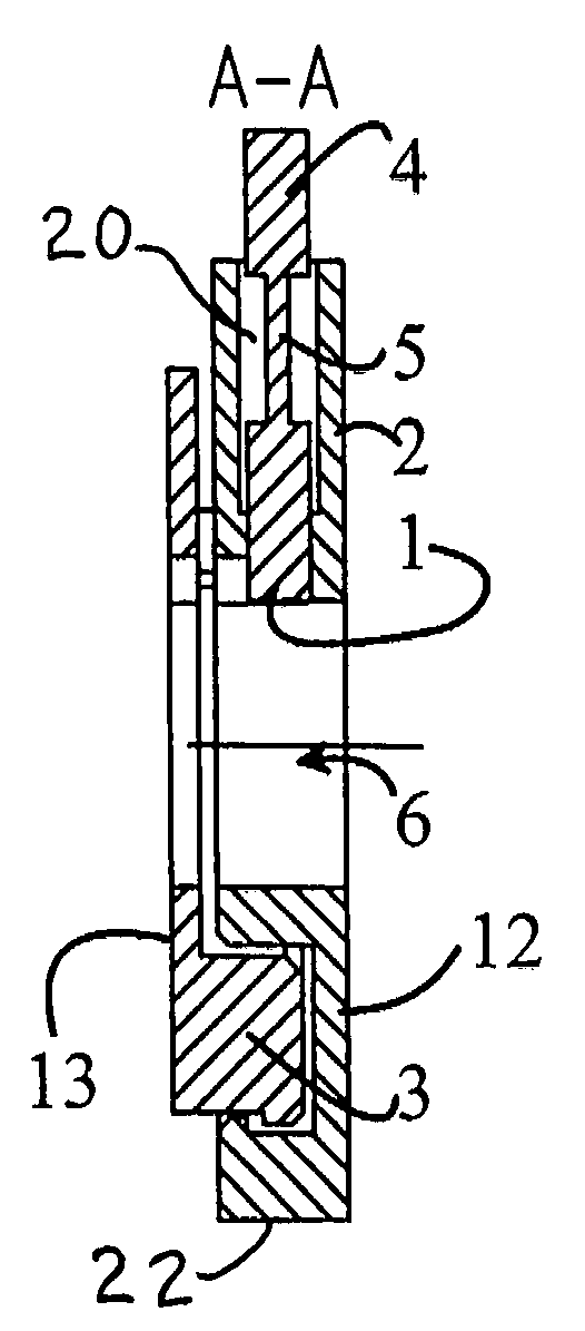
[0029]FIG. 3 shows the construction of the measuring electrode 10 in greater detail. The measuring opening 6 extends through the entir...


PUM


Abstract

The invention relates to an electrode structure (10) for attachment to a more extensive measuring structure (11), in order to measure electrical responses from the human body. The electrode structure (10) includes a conductive electrode (1). According to the invention, the electrode (1) is shaped to be thin in the thickness direction of the electrode structure (10), and the electrode structure (10) is equipped with a hole (6) and the electrode (1) is located at the edge of the hole (6), in such a way that its longitudinal axis is essentially parallel to the plane of the measurement subject.

Description

FIELD OF THE INVENTION[0001]The present invention relates to an electrode structure for attachment to a more extensive measuring structure, in order to measure electrical responses from the human body.[0002]The invention also relates to a measuring cap and a manufacturing method.BACKGROUND OF THE INVENTION[0003]According to the prior art, measurements made from the surface of the head in particular are made using silver electrodes for measuring electrical responses, for example, in TMS (transcranial magnetic stimulation) tests, in which an electromagnetic pulse is directed to the brain and the response it creates is measured using electroencephalograph (EEG) measuring equipment. In practice, electrically polarizing interfaces arise between the different materials in the silver electrodes according to the prior art and lead to interference signals that diminish the accuracy of the measurement.[0004]The silver electrodes are chloridized, in an attempt to eliminate this phenomenon. Des...

Claims


Application Information

Patent Timeline
IPC IPC(8): A61B5/04A61B5/296
CPCA61B5/0478A61B5/0492A61B2562/0215A61B5/291A61B5/296A61B5/25
Inventor HANNULA, HENRIAHO, MATTIOLLIKAINEN, MARKO
Owner NEXSTIM
Learn More