
Alert condition system usable for personnel monitoring

Inactive Publication Date: 2001-12-11
SENIOR TECH
View PDF5 Cites 47 Cited by
  • Summary
  • Abstract
  • Description
  • Claims
  • Application Information

AI Technical Summary

Benefits of technology

From the above description, it can be understood that the alert system of this invention has several advantages, such as: (1) it provides a warning that will cause persons monitoring a passageway to be alert to a possible exit of an unauthorized person or object; (2) it can compensate to some extent for a malfunction of the alarm condition because persons will be put on guard by the alert condition; and (3) it is inexpensive and reliable, utilizing mainly parts and equipment already present in many existing monitoring systems to provide the extra alert condition.

Problems solved by technology

The prior art personnel monitoring system of this class may generate a signal when the personnel being monitored are near a passageway but do not provide an alarm or warning unless a monitored person gives further indications of trying to go through the passageway.
The prior art personnel monitoring systems have several disadvantages, such as for example: (1) they do not provide advanced warning that a monitored person may be about to go through the passageway; (2) the signals may be given at a time when the central station doing the monitoring is unattended, thus permitting the persons to proceed a substantial distance before it is detected that they have left: (3) the systems can be defeated by a careful person attempting to avoid detection until the last minute and then quickly proceed through the passageway; and (4) the systems are susceptible to failure because of a temporary malfunction because there may be inadequate warning.
While such a system could be employed to detect a person who is spending a prolonged time attempting to exit through the passageway, they have not been applied in this manner even though they have been available for a substantial number of years in other localities.
Moreover, they are not adapted to merely alert personnel to wait for an actual attempt to go through the passageway but instead the second signal is provided only to indicate that someone has been waiting a long time for service.

Method used


Image

  • Alert condition system usable for personnel monitoring
  • Alert condition system usable for personnel monitoring
  • Alert condition system usable for personnel monitoring

Examples


Embodiment Construction

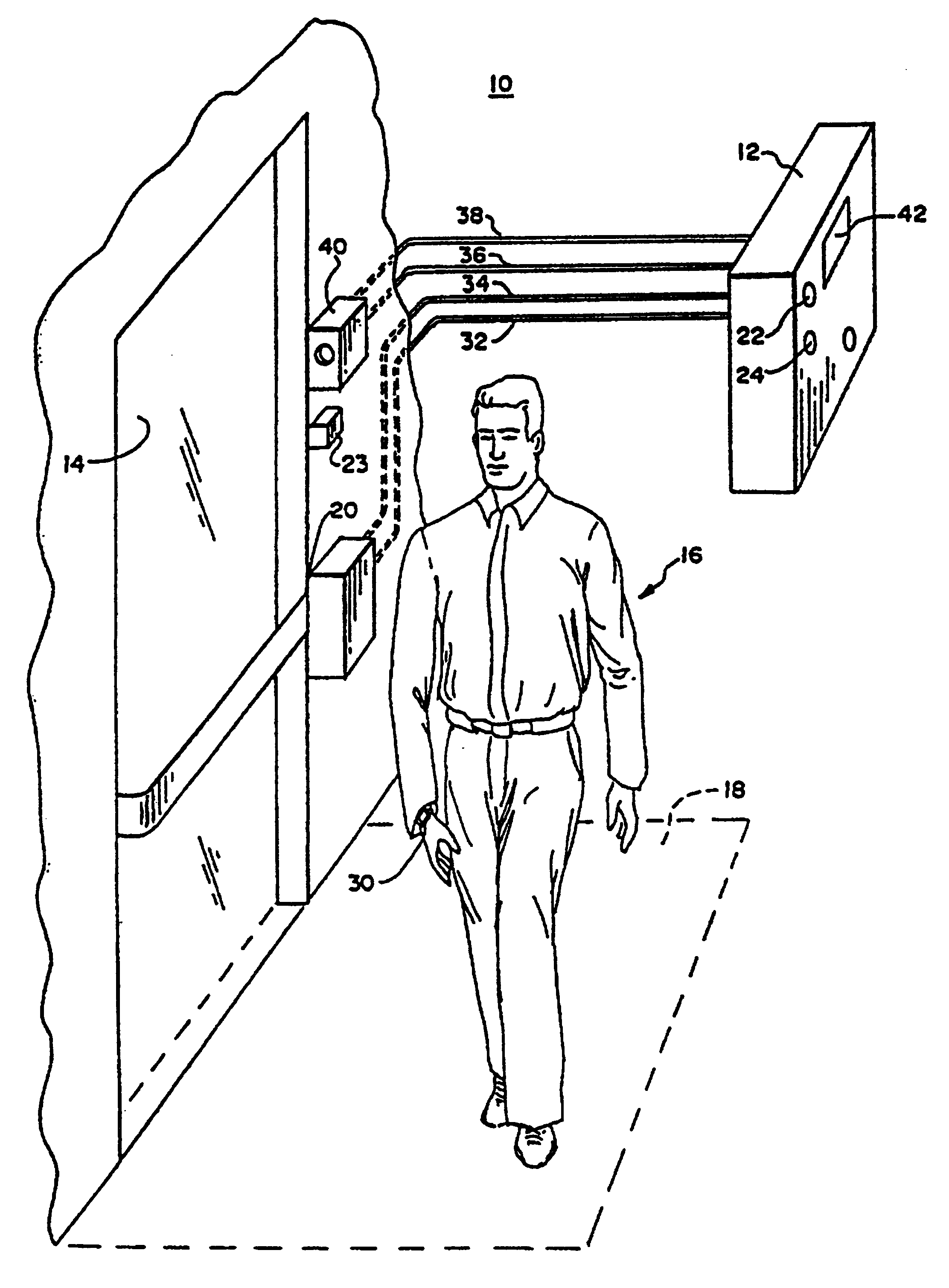
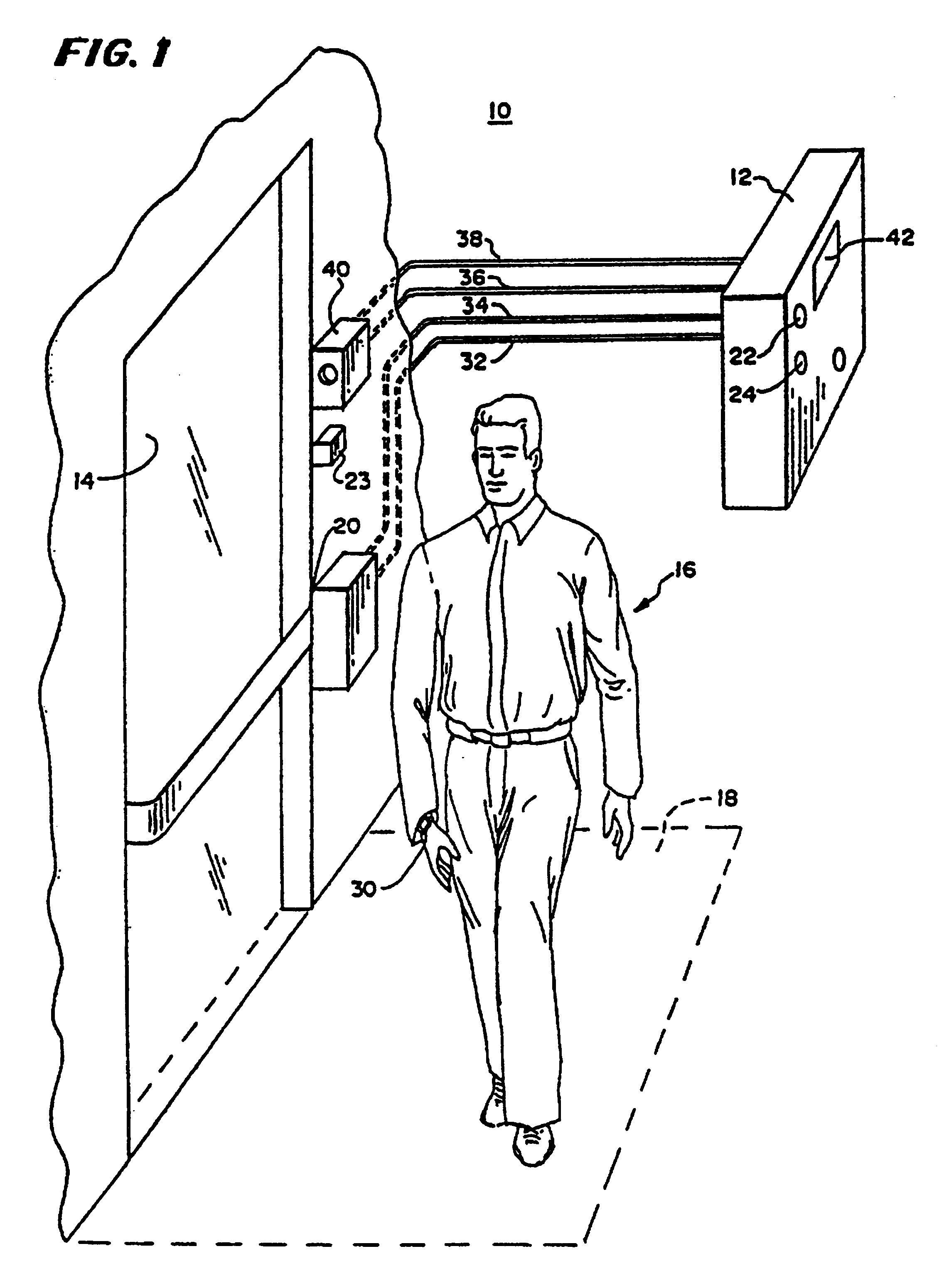
In FIG. 1, there is shown an alert system 10 having a monitoring station 12, a monitored passageway 14, and a monitored subject 16 which, in the embodiment of FIG. 1, is a patient not authorized to leave the premises. The monitored passageway 14 has a first region 18 in front of the passageway 14 and a second region or condition 20 within the passageway 14 or connected to it. The monitoring station 12 includes a first alert signal means 22 and a second warning or alarm signal means 24.

The alert system 10 is adapted to generate a first signal 22 when the patient 16 is within the first region 18 and to generate a second signal 24 when the patient 16 is in or actuates the second region or condition 20 by opening a door in the passageway 14, although it could be actuated by other means such as by the strength of a signal generated at that location or a pressure pad or photocell detector or infrared sensor or any other detector.

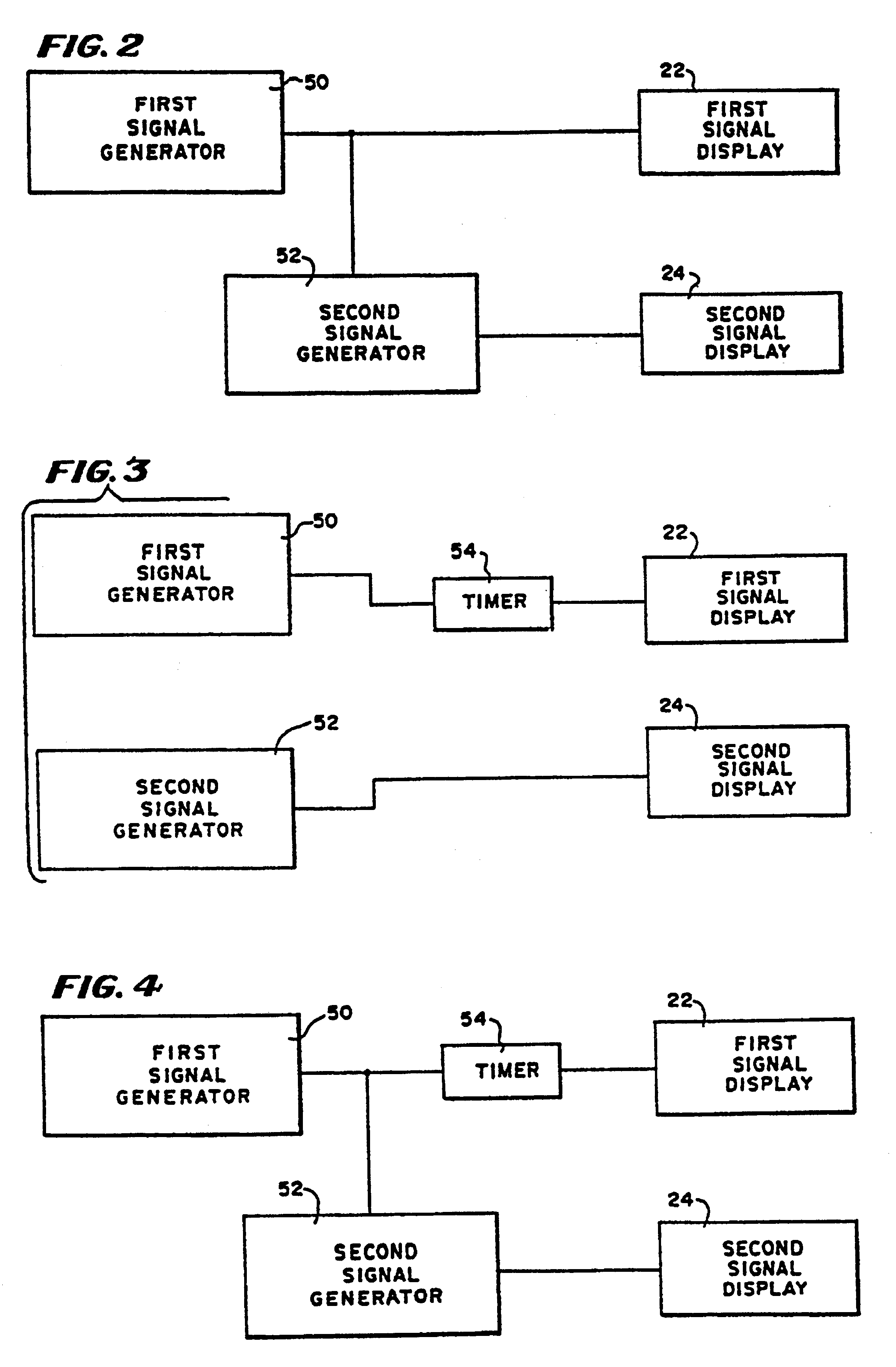
To provide an alert signal and / or an alarm signal, the monit...


PUM


Abstract

To generate an alert signal indicating that an unauthorized subject is in a first region within seven feet of a passageway, a radio transmitter is worn by the subject and received by a receiver at the passageway. A second signal is generated upon satisfaction of a second condition, such as an open door at the passageway, which second signal indicates the likelihood of the subject passing through the passageway. A first display indicates if the first signal is present and a second signal if the second condition occurs.

Description

BACKGROUND OF THE INVENTIONThis invention relates to apparatuses and methods for monitoring personnel.In one class of personnel monitoring system, a detector is positioned near exits or in passageways to determine when a person or an object is moving through the passageway or door. At that time, a signal is transmitted to a monitoring station indicating that a person or object is going through the door. Among other uses, such systems are used as security systems to determine if unauthorized patients are leaving a nursing home or the like. One such system is disclosed in U.S. Pat. No. 4,095,214.In some such systems, a first signal is generated when the patient enters a first region. If a second condition occurs, such as the opening of a door, an alarm signal is given. A system of this type is disclosed in U.S. Pat. No. 4,682,155. In some of the known systems, a person carries an active device such as a transmitter, and an others, the person carries a passive device which receives sig...

Claims


Application Information

Patent Timeline
IPC IPC(8): G07C9/00G08B13/08
CPCG08B13/08G07C9/28
Inventor BRASCH, JOHN J.CROSS, ALAN W.
Owner SENIOR TECH
Learn More