HVAC fan-powered terminal unit having preset fan CFM

a terminal unit and fan technology, applied in the field of control of fan powered terminal units, can solve the problems of high cost of hvac system setup, inability to easily determine the width of pulses of pwm signal, and terminal units currently using ecm motors must still undergo high-cost air flow balancing procedures

Inactive Publication Date: 2004-01-27
NAILOR INDS OF TEXAS
View PDF15 Cites 146 Cited by
  • Summary
  • Abstract
  • Description
  • Claims
  • Application Information

AI Technical Summary

Problems solved by technology

This portion of the HVAC system set-up adds substantially to the cost with labor related costs currently running around $40 to $60 dollars per terminal unit.
Unfortunately, the width of the pulses of the PWM signal can not be readily determined without equipment which is not normally available to manufacturing personnel and HVAC contractors.
Accordingly, while the ECM motors offer the promise of being able to preset the air flow for terminal units on the manufacturing floor before shipment and also once installed to accommodate changing conditions of a HVAC system, terminal units currently using ECM motors must still undergo the high cost air flow balancing procedures.

Method used


Image

  • HVAC fan-powered terminal unit having preset fan CFM
  • HVAC fan-powered terminal unit having preset fan CFM
  • HVAC fan-powered terminal unit having preset fan CFM

Examples


Embodiment Construction

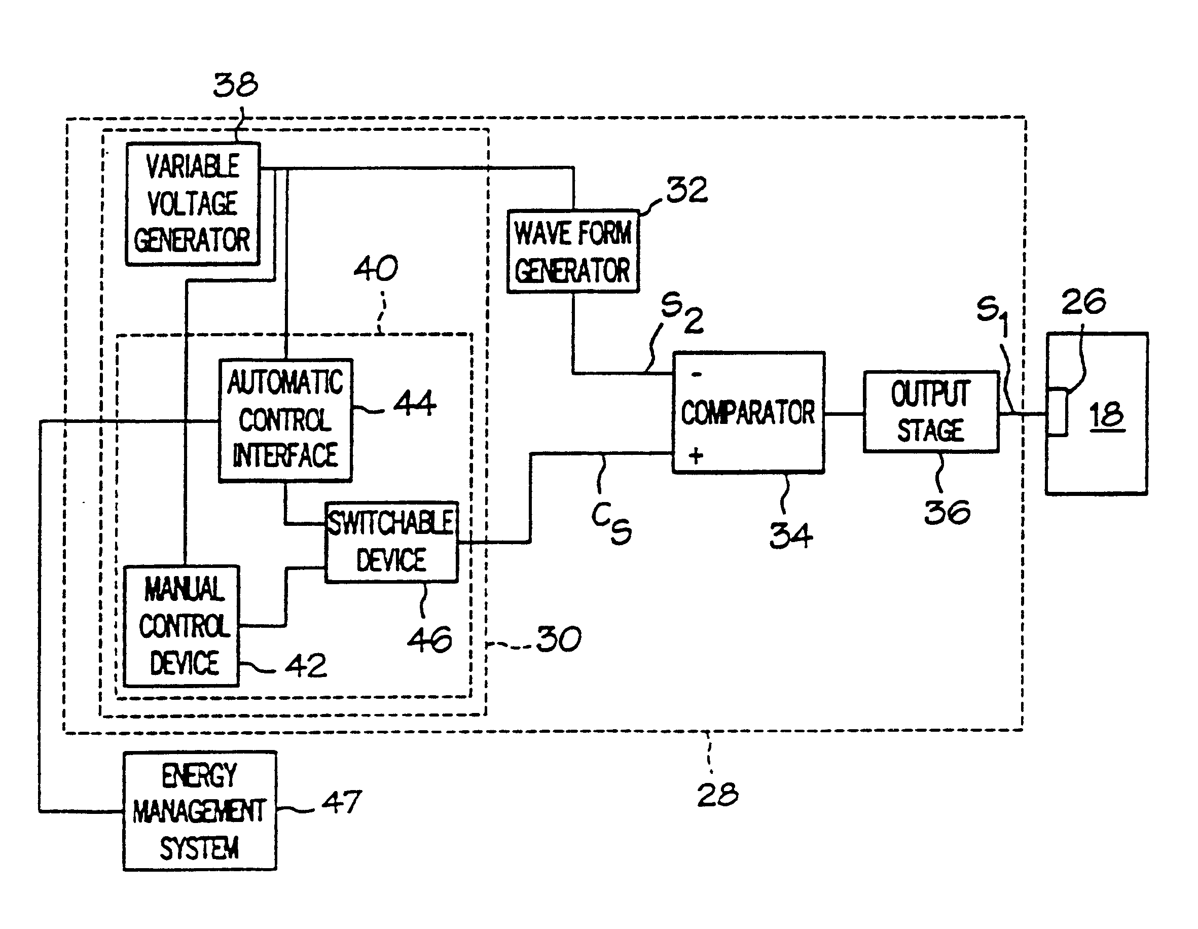
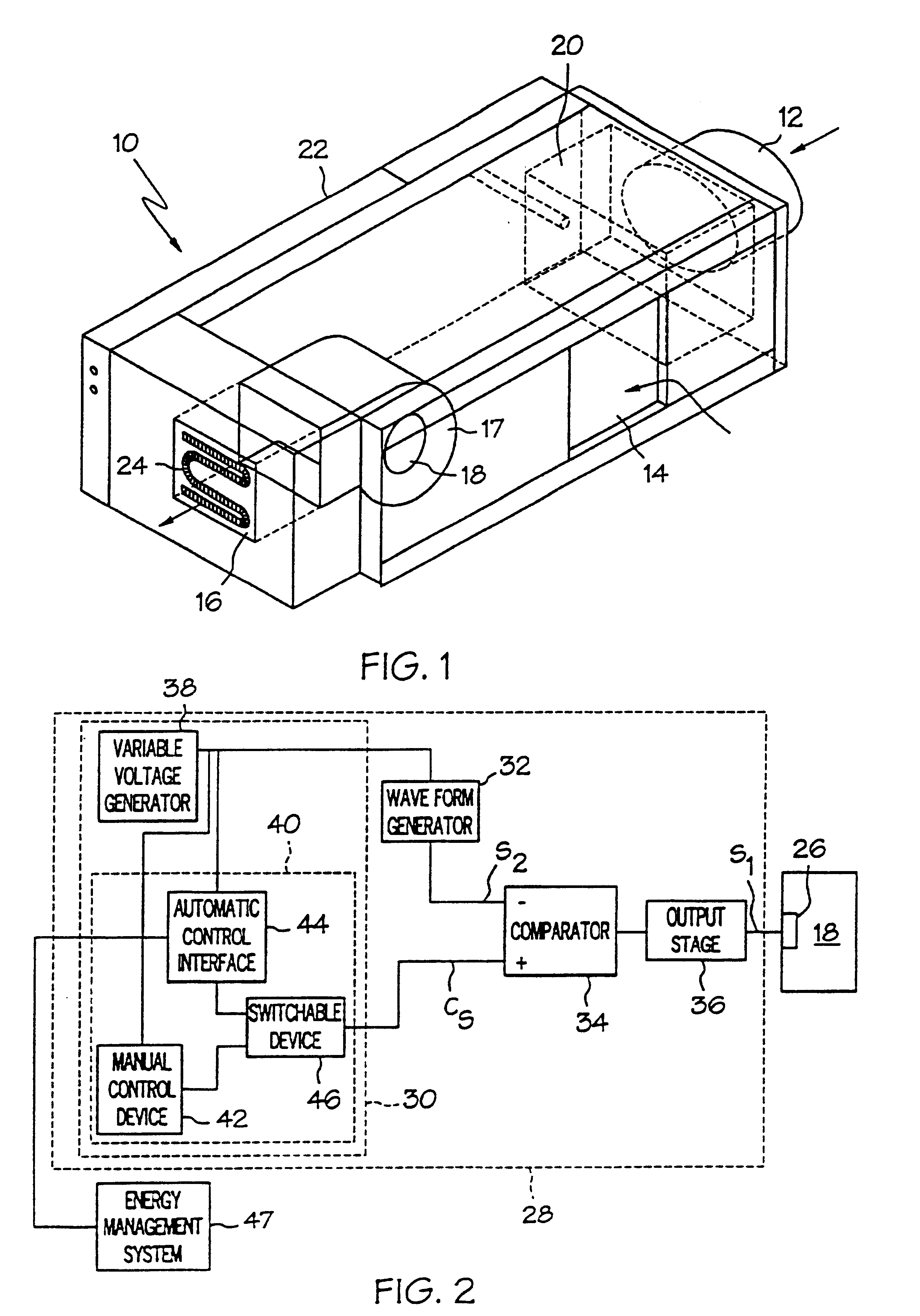
While the present invention is applicable in general to HVAC systems, it will be described herein with reference to a fan-powered terminal unit for use in a commercial building for which it is particularly attractive and in which it is initially being utilized. Referring to FIG. 1, a fan-powered terminal unit 10 is provided having a primary air duct 12, an induced plenum air inlet 14 and a discharge duct 16. The primary air duct 12 receives primary air from the ventilation system (not shown) while the induced plenum air inlet 14 receives warmer plenum air from the building core plenum space (not shown). The warmer plenum air is generated by the free heat derived from people, lighting and other equipment in the building. The primary air duct 12 and the induced plenum air inlet 14 are arranged in series for delivering a desired air flow or cfm to a perimeter zone of a building (not shown) through the discharge duct 16. This type of fan-powered terminal unit 10 is also known as a serie...


PUM


Abstract

An arrangement is disclosed for controlling fan motors in fan-powered terminal units which permit the air flow of the terminal units to be factory preset and reset using a voltmeter. The fan motor is responsive to the pulse width of pulses of a pulse width modulated signal to provide an air flow which is proportional to the pulse width. By adjusting the pulse width, the air flow may be set as desired. A pulse width modulated signal having pulses with a set amplitude and frequency is generated. The dc voltage of the pulse width modulated signal is measured using a voltmeter. As the pulses have a set amplitude and frequency, the pulse width of the pulses may be adjusted by controlling the dc voltage of the pulse width modulated signal. The fan motor is programmed to deliver the set air flow over a range of static pressures.

Description

BACKGROUND OF THE INVENTIONThe present invention relates in general to heating, ventilating and air-conditioning (HVAC) and, more particularly, to control of a fan powered terminal unit wherein the fan air flow or cubic feet per minute (CFM) can be preset without regard for the installation specifics of the HVAC system in which the terminal unit is to be used. While the fan control will be described with reference to a fan powered terminal unit for which the present invention is initially being applied, it is to be understood that the fan control arrangement of the present application may be used in a variety of HVAC applications including, for example, venting hoods, exhaust fans, supply fans and fan coils.Fan-powered terminal units which provide variable air volume (VAV) are used for both cooling and heating of perimeter zones of a building. The terminal units use the free heat derived from lighting, people and other equipment within the building by inducing this warmer air from a...

Claims


Application Information

Patent Timeline
Patent Type & Authority Patents(United States)
IPC IPC(8): F24F11/00G05D7/06
CPCG05D7/0676F24F11/77Y02B30/70
Inventor FARIS, EUGENE WILLIAM MICHAELCROWE, ROBERT CLAYTON
Owner NAILOR INDS OF TEXAS
Why Eureka
Try Eureka