
Method and device for detecting resistance

A measurement method and technology of a measurement device, which is applied in the direction of a measurement device, measurement of electrical variables, measurement of resistance/reactance/impedance, etc., can solve problems such as long adjustment time, temperature rise, and difficulty in measuring continuous variation of resistance value

Inactive Publication Date: 2006-03-22
UNIV OF SCI & TECH BEIJING
View PDF0 Cites 38 Cited by
  • Summary
  • Abstract
  • Description
  • Claims
  • Application Information

AI Technical Summary

Problems solved by technology

In actual use, it is found that the double-arm bridge method has the following disadvantages: the measurement accuracy of μΩ level resistance is not enough, usually the highest measurement accuracy is 1μΩ, and its error is more positive than the true value of resistance; when measuring low resistance, due to the need to use Relatively large power supply current, so the DC stabilized power supply is large in size, heavy in weight, and thick in test wires, which brings inconvenience to testing and carrying; during the test process, it takes a long time to adjust, and it is impossible to quickly measure the resistance value , thus making it difficult to measure the continuous variation of the resistance value; during the measurement process, due to the large test current and long adjustment time, the temperature of the object under test will rise, making the test conditions unstable, resulting in a comprehensive test error
[0008] The above-mentioned traditional volt-ampere method, bridge method, and potentiometer method are not suitable for this special occasion and the resistance measurement of the conductor under special requirements.

Method used


Image

  • Method and device for detecting resistance
  • Method and device for detecting resistance
  • Method and device for detecting resistance

Examples


Embodiment Construction

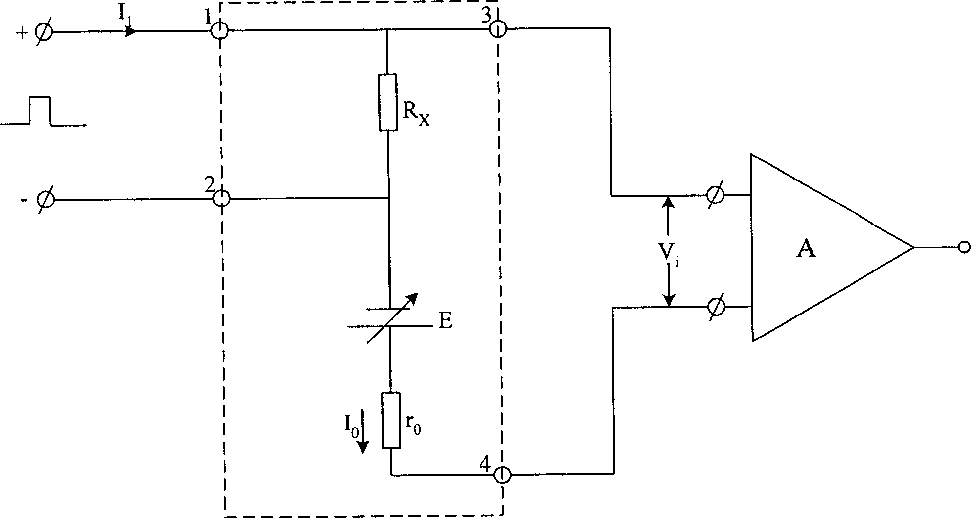
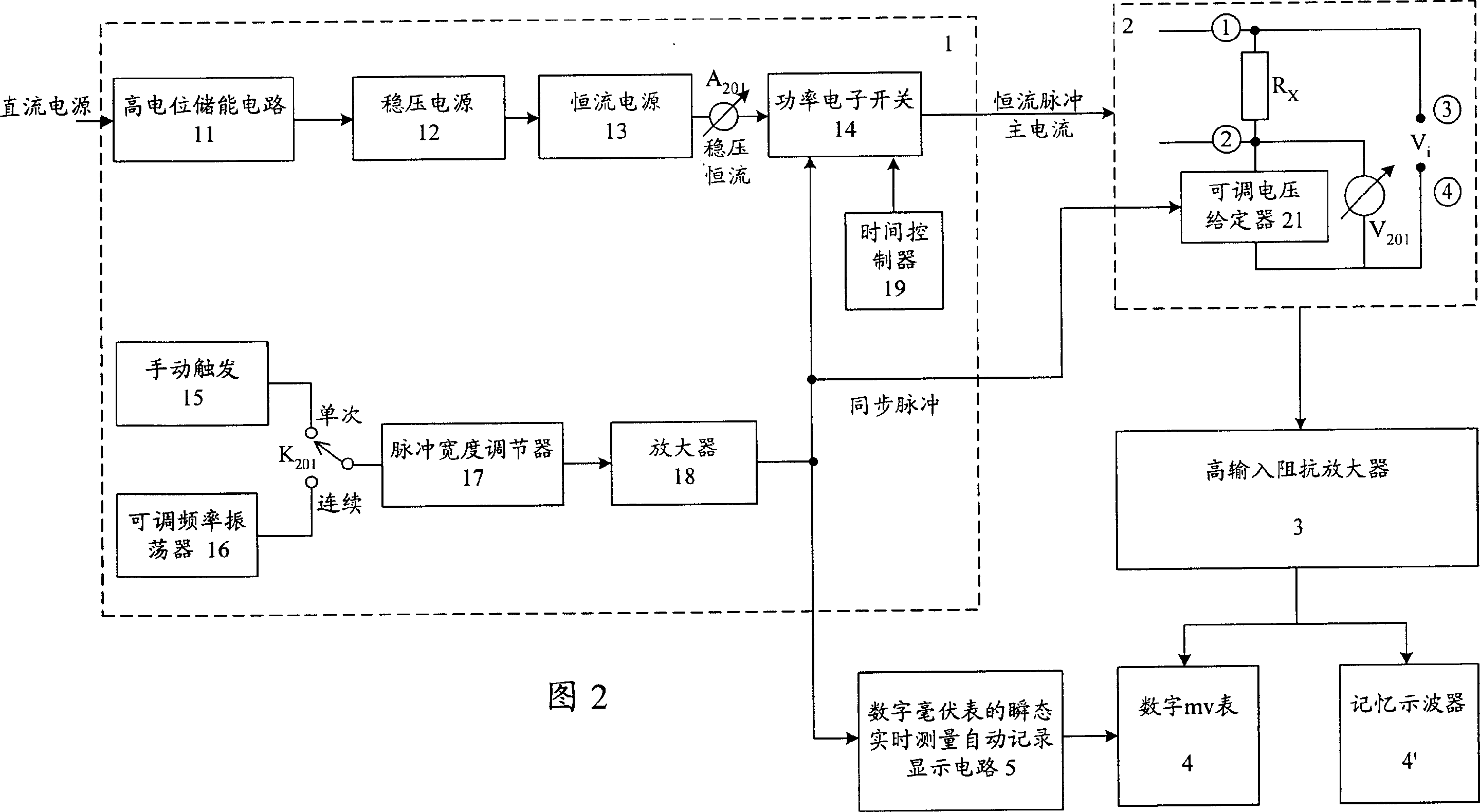
[0046] The four-terminal network constant-current pulse method of the present invention is an improvement on the basis of the four-probe method or the constant-current four-wire method. According to Ohm's law R=V / I, the essence of measuring resistance is to measure the voltage drop V of the current I on the resistance R, and then through the known current I, the resistance R can be obtained, so I must be a constant current. However, if I is too small, the obtained V is also small, and the difficulty of realizing the detection device increases correspondingly, and if I is too large, the temperature rise on the resistance will be caused. The four-terminal network constant current pulse method proposed by the present invention solves this contradiction. A large current is generated at the moment of the pulse, and due to the extremely short time, no obvious temperature rise will be caused on the measured object. The specific test needs to meet the following four conditions: the me...


PUM


Abstract

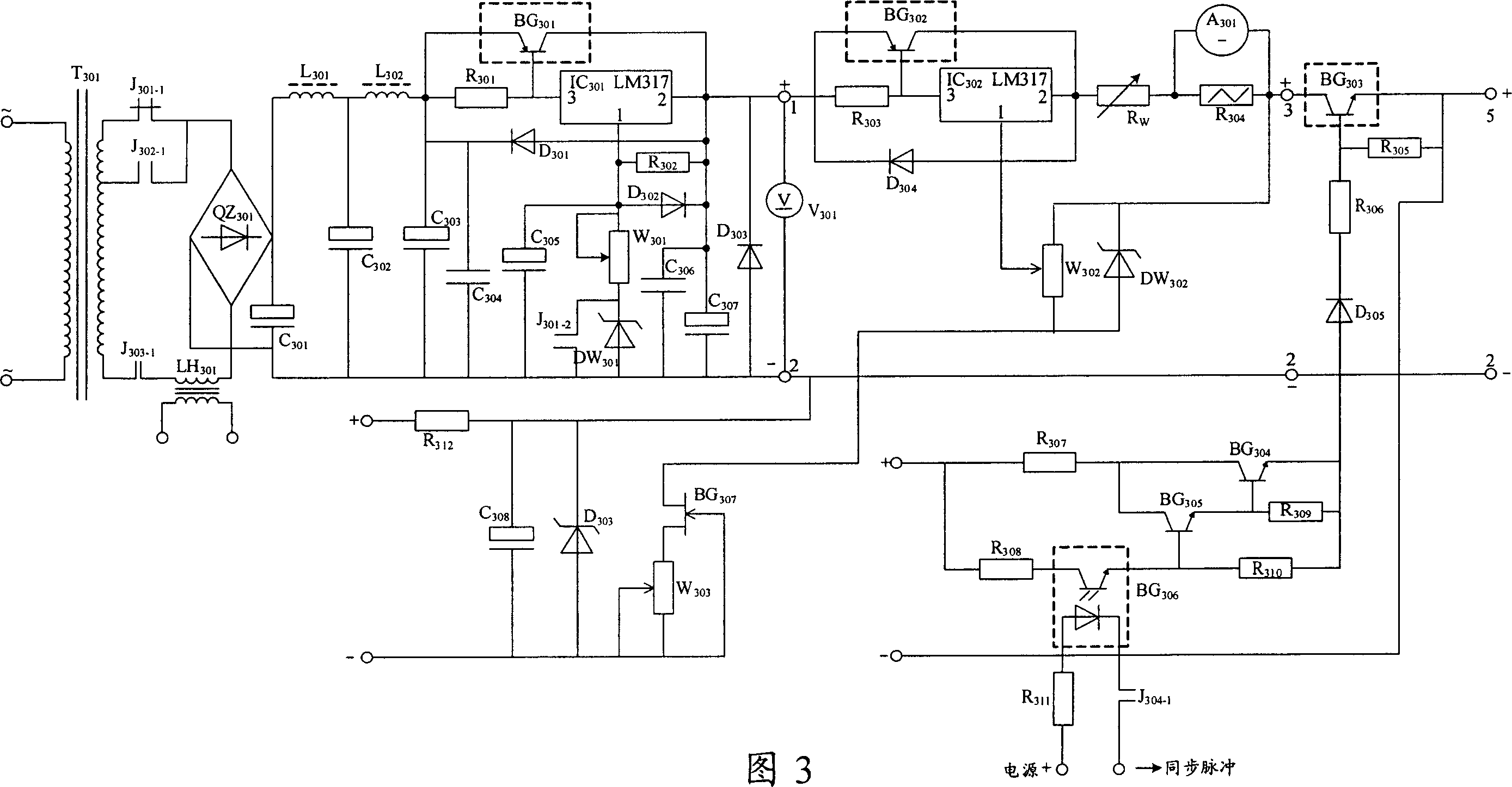
The resistance measuring method and device is especially suitable for quickly measuring small resistance and varying resistance according with Ohmí»s law. The resistance measuring device includes constant-current pulse source, four-end network containing the measured resistance, high input impedance amplifier, real-time measuring and automatic recording display circuit for voltmeter, and digital millivoltmeter. It measures resistance through generating constant-current pulse, producing voltage drop on the measured resistance, amplifying the voltage drop, automatic conversion between reading state and holding memory state and recording and displaying voltage drop. During measuring resistance change, given voltage synchronous with the constant-current pulse is added into the four-end network, and the varying voltage drop the constant-current pulse produces on the measured resistance is measured by means of potential approaching method and further differential method.

Description

technical field [0001] The present invention relates to a measurement method and a measurement device, more specifically to a resistance measurement method and a measurement device, especially suitable for transient measurement of low resistance of solid or liquid conductors, when the measured object changes with the environment such as temperature The measurement of the small change resistance value, and complete the fast resistance measurement of the measured object in an instant. Background technique [0002] Resistance is a physical parameter of various materials, which is defined as the ratio of the voltage drop V on the measured object when a constant current I passes through the measured object to the constant current I, expressed as R=V / I. [0003] At present, the commonly used methods for measuring the resistance of conductor materials can be mainly divided into three categories, one is the direct reading method, such as the volt-ampere method, and the other is the ...

Claims


Application Information

Patent Timeline
IPC IPC(8): G01R27/02G01R27/14
Inventor 储少军杨涛
Owner UNIV OF SCI & TECH BEIJING
Learn More