Knuckle hub assembly and method for making same

a technology of hub assembly and knuckle, which is applied in the direction of manufacturing tools, brake discs, transportation and packaging, etc., can solve the problems of performance and run-out problems, the approach has not found widespread acceptance, and the manufacturers have faced difficulties in achieving enhanced control over these tolerances. achieve the effect of reducing the lateral run-out of the hub

Inactive Publication Date: 2011-11-15
ALUDYNE NORTH AMERICA INC
View PDF37 Cites 6 Cited by
  • Summary
  • Abstract
  • Description
  • Claims
  • Application Information

AI Technical Summary

Benefits of technology

It is therefore an object of the present invention to provide a knuckle / hub assembly and a method for manufacturing same that provides reduced wheel hub lateral run-out.
In accordance with another object of the present invention, an assembly for holding a knuckle / hub assembly while it is final finished is provided. The assembly includes a standard lathe machine with a fixture for clamping and locating the knuckle / hub assembly. The fixture applies a clamping force to the wheel hub and the inner race of the bearing to generate a pre-load on the bearing. The fixture also holds the knuckle in place so that the wheel hub may be rotated. Thereafter, the inner and outer surfaces of the flange face are final finished so that they are flat and co-planar with respect to each other. These two surfaces have minimal run-out when measured back to the knuckle / hub assembly's axis of rotation.

Problems solved by technology

Although efforts to integrate these components have been proposed, such an approach has not found widespread acceptance.
However, manufacturers have faced difficulties in achieving enhanced control over these tolerances due to the influence of several factors.
However, despite the fact that the tolerances and dimensional characteristics of the rotors have improved, performance and run-out problems still exist.
These run-out problems are due in large part to other components of the wheel end assembly, including the bearing / hub assembly, which is comprised of a wheel hub and a bearing or the knuckle / hub assembly, which is comprised of a knuckle, a heel hub, and a bearing.
While the tolerances of each part can be reduced when they are separately machined, when the parts are assembled, the combined tolerances stack up, causing run-out that is still relatively significant.
Further, the installation and press condition of the wheel bolts, the assembly process of the knuckle / hub assembly, and improperly pre-loaded bearings, can all cause misalignment of the hub surface with respect to the rotor and thus cause unacceptable run-out.
This run-out can cause premature failure of the brake lining due to uneven wear which requires premature replacement of the brake lining at an increased expense.
Further, problems due to run-out include, brake judder, steering wheel “nibble” and pedal pulses felt by the user, and warped rotors which result in brake noise and uneven stopping.
Presently available manufacturing methods and designs of knuckle hub assemblies limit the accuracy to which lateral run-out of braking surfaces can be controlled.
These methods and designs are also insufficient to solve the problems associated with run-out, as discussed above.
These methods, however, do not solve the run-out problems due to the factors discussed above, including stack-up tolerances, turning process variations, and wheel bolt and bearing installations.
The “stack up” of tolerance variations related to such an approach is still significant and provides only limited system improvement at an increased manufacturing cost.
This, however, significantly increases the difficulty in the assembly process as well as increases the manufacturing cost.
Further, this option does not provide the desired reduction in system run-out.

Method used


Image

  • Knuckle hub assembly and method for making same
  • Knuckle hub assembly and method for making same
  • Knuckle hub assembly and method for making same

Examples


Embodiment Construction

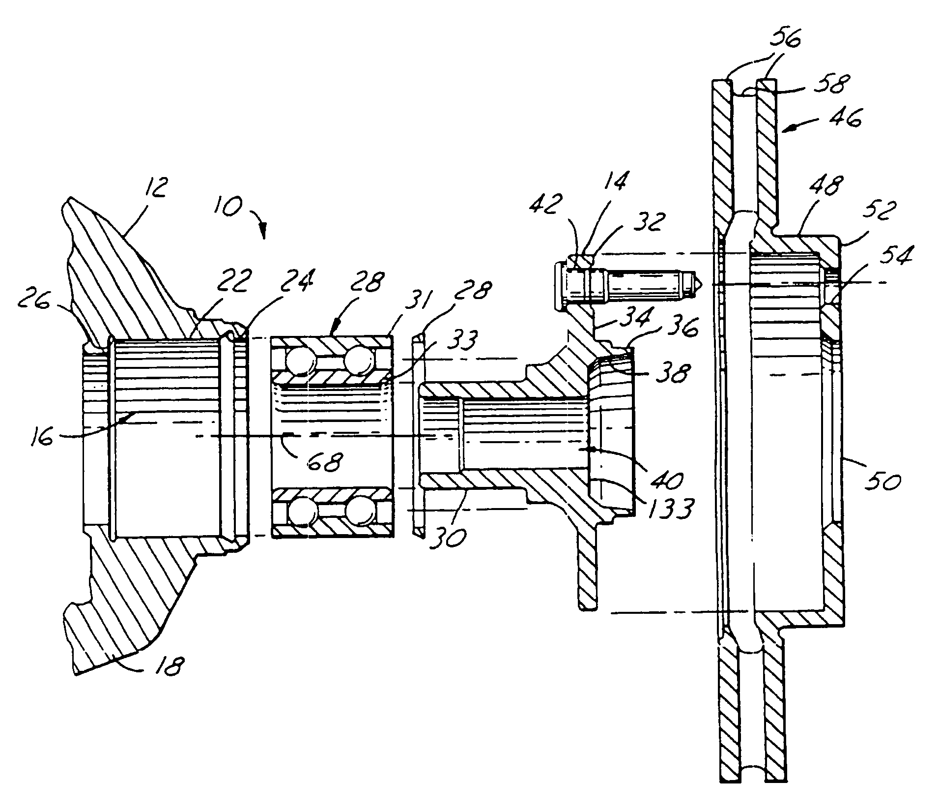
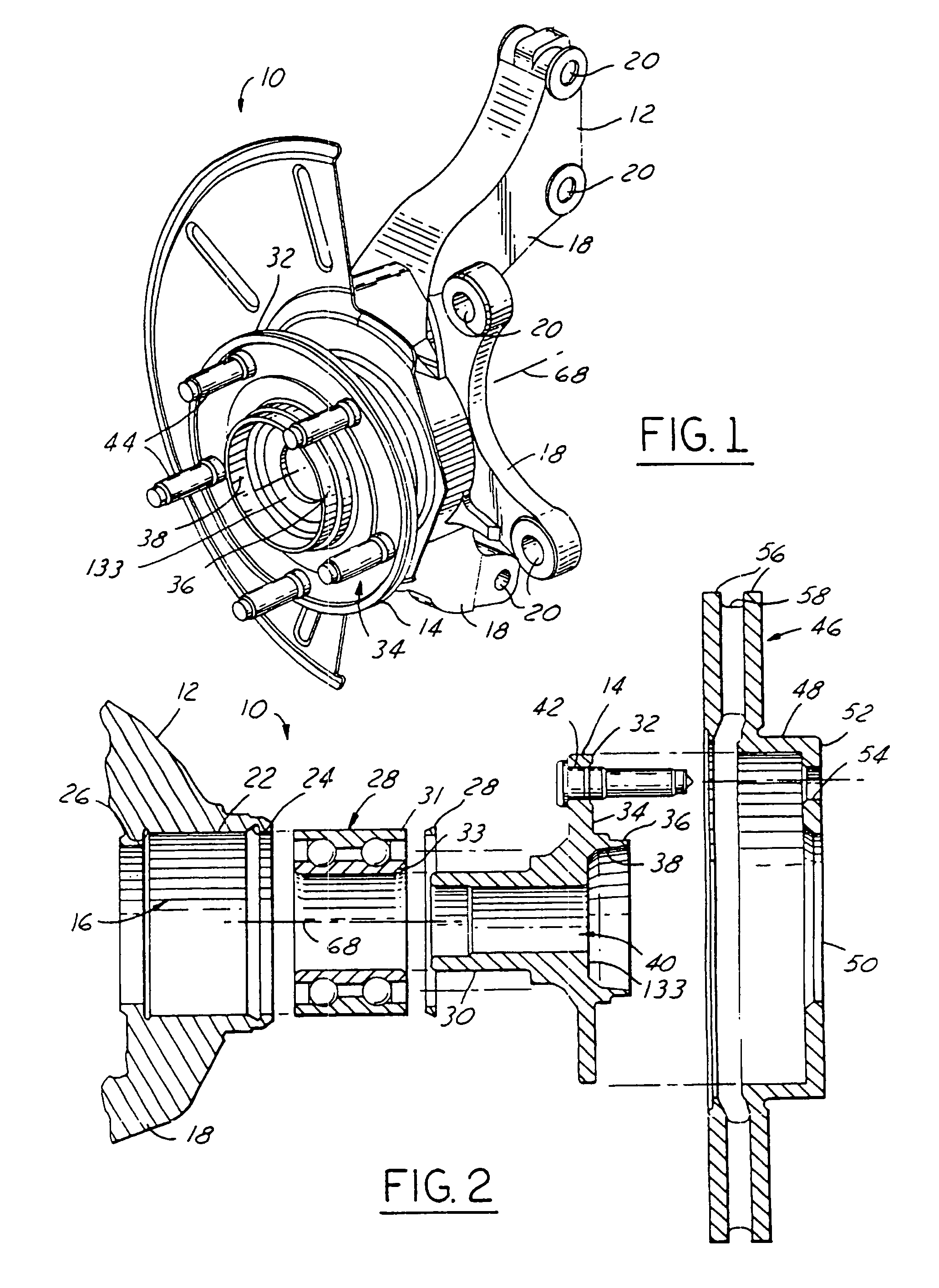
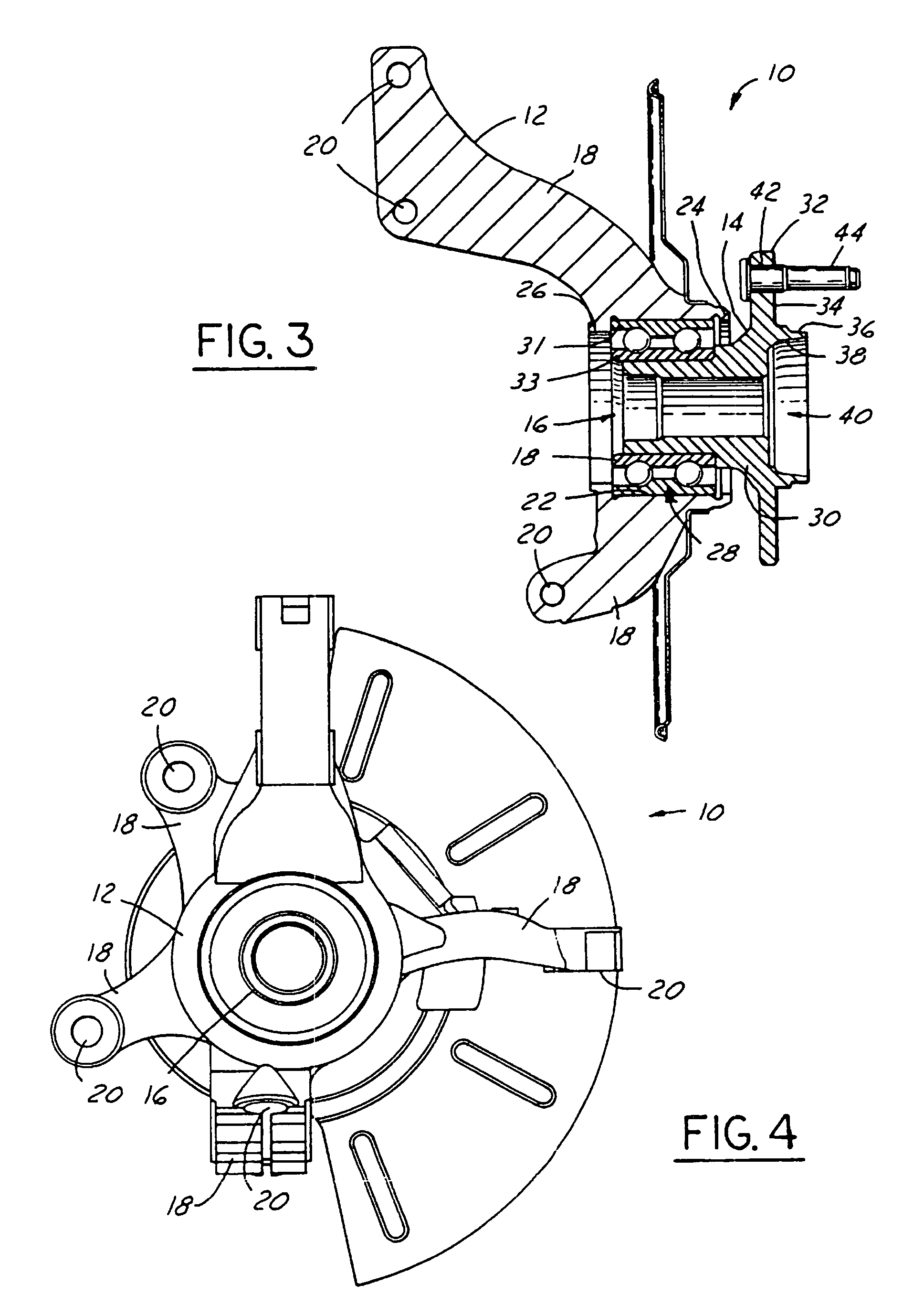
FIGS. 1 through 4 illustrate a preferred knuckle / hub assembly, as generally indicated by reference number 10, in accordance with the present invention. The assembly 10 is comprised of a variety of components, including a knuckle 12 and a wheel hub 14. The knuckle 12 is preferably constructed of metal and is generally formed by casting while the wheel hub 14 is preferably constructed of metal. The knuckle and hub can obviously be formed of other materials. The knuckle 12 preferably has a generally circular bore 16 formed therein and a plurality of outwardly extending appendages 18 that attach to the vehicle through a plurality of apertures 20 formed in the plurality of legs 18, as is well known in the art.

The bore 16 has a recess 22 formed therein bounded by an upper snap ring groove 24 and a lower snap ring 26 or shoulder for receiving a bearing 28 press fit therein. A snap ring 29 is preferably press fit or otherwise secured into the upper snap ring groove 24 prior to engagement of...


PUM

PropertyMeasurementUnit
flatnessaaaaaaaaaa
flatnessaaaaaaaaaa
flatnessaaaaaaaaaa

Abstract

A knuckle hub assembly (10) and a method for manufacturing same whereby brake run out is produced includes a knuckle (12), a bearing (28) press fit into the knuckle (12), and a wheel hub (14) coupled to the bearing (28) and rotateable with respect to the knuckle (12). The wheel hub (14) has a flange surface (34) having a relief channel (60) formed therein. A plurality of wheel studs (44) are press fit into bolt opening (42) formed in the relief channel (60). This arrangement provides a flat flange surface (34) for mating with a rotor (42) to minimize brake run out. The knuckle hub assembly (10) is mounted into a floating tool for finish turning of the flange surface (34) to provide minimal run out and maximum flatness.

Description

TECHNICAL FIELDThe present invention relates generally to motor vehicle wheel end components. More particularly, the present invention relates to a knuckle / hub assembly having a unique assembly and manufacturing process for reducing lateral run-out and a unique apparatus for machining the rotor-mounting flange surface of the wheel hub.BACKGROUND ART Most motor vehicles today include disc brake systems for the front axle wheel assemblies and many further include disc brakes at the rear axle position. The disc brake rotor is a circular metal disc having opposed braking surfaces that are clamped by brake pads carried by a brake caliper to exert a braking effect. The wheel hub typically incorporates an anti-friction wheel bearing assembly in which one race of the bearing is coupled to the vehicle suspension and the other rotationally mounts the wheel hub, the brake rotor and wheel. Ordinarily, the rotating components of the rotor and hub assembly are manufactured separately and assemble...

Claims


Application Information

Patent Timeline
Patent Type & Authority Patents(United States)
IPC IPC(8): B21K1/40B60B27/00B23B5/04B62D7/18F16D65/12
CPCB23B5/04B62D7/18F16D65/12B23B2235/04B23B2235/21F16D2065/1384Y10T29/53104Y10T29/49535Y10T279/33Y10T29/49533Y10T82/26Y10T29/497Y10T29/49696Y10T82/266Y10T29/49904B60B27/00
Inventor BRINKER, DANIELELZERMAN, BRIANMERRILL, BENVELDMAN, ROBERT
Owner ALUDYNE NORTH AMERICA INC
Why Eureka
Try Eureka