
Radial lip seal device

A technology of sealing device and radial shaft, which is applied in the direction of engine sealing, engine components, mechanical equipment, etc., can solve the problems of complex structure and large space, and achieve the effect of simple structure

Active Publication Date: 2007-09-19
CARL FREUDENBERG KG
View PDF7 Cites 0 Cited by
  • Summary
  • Abstract
  • Description
  • Claims
  • Application Information

AI Technical Summary

Problems solved by technology

The structure of this sealing device is also very complicated and requires a large space

Method used


Image

  • Radial lip seal device
  • Radial lip seal device
  • Radial lip seal device

Examples


Embodiment Construction

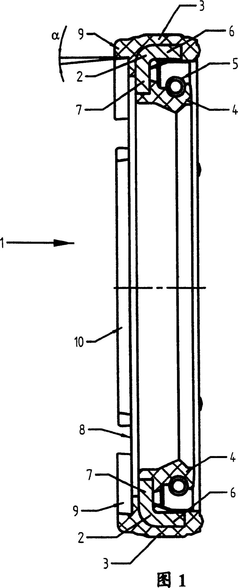
[0017] FIG. 1 shows a sealing ring 1 for a radial shaft seal. The radial shaft sealing ring 1 forms a sealing assembly comprising a base body 2 of metal with an outer adhesive layer 3 of elastomer and a radially inwardly facing sealing lip 4 . The sealing lip 4 is likewise made of an elastomer and is additionally pressed against a shaft (not shown in detail) via a spring ring 5 . Seen in cross section, the base body 2 has an axial branch 6 and a radial branch 7 . Branches 6 and 7 are of equal length in the example shown.

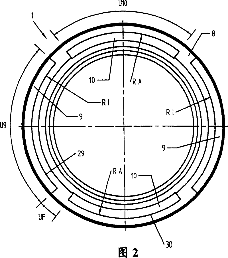
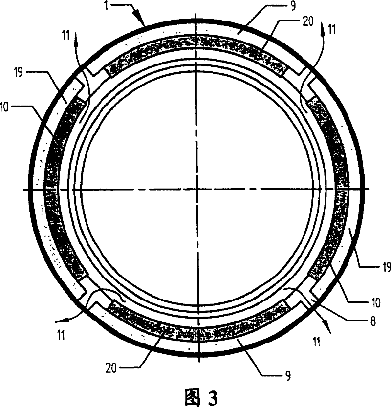
[0018] The inner surface 8 of the sealing ring 1 after the assembly of the two sealing rings is provided with four annular segments 9 and 10 which, in the assembled state of the two sealing rings 1 , engage with each other in a non-positive and form-fitting manner. Two of the ring segments 9 are offset radially outward and are referred to as outer ring segments 9 , while the inner ring segment 10 is offset radially inward. The associated second sealing ri...


PUM


Abstract

The invention relates to a radial axis sealing device which has two identical sealing rings (1) which can be mutually connected and are characterized in that the surfaces (8) attached to each other are provided with two rows of curved projections (9 and 10) which are joined by force or locked under the equipment of the sealing rings (1).

Description

technical field [0001] The invention relates to a radial shaft seal for sealing two media, which has two radial shaft seal rings which are designed to be identical and can be plugged into one another. Background technique [0002] A shaft seal for sealing two media by means of two radial shaft seal rings is known from DE 2351767, wherein at least one seal ring has a housing that is angled in cross section, so that the seal rings can Plugged into each other, in this type of sealing arrangement a negative pressure or a positive pressure can build up between the sealing lips, so that venting is required from the cavity formed by the sealing rings. For this reason, the known shaft seal has radially and axially extending channels in the region of the housing surfaces where the two radial shaft seal rings contact each other. In this way, the air-inflated portion and the air-vented portion are formed. Overall, however, the seal has a very complex structure and requires a large am...

Claims


Application Information

Patent Timeline
Patent Type & Authority Patents(China)
IPC IPC(8): F16J15/32F16J15/00
CPCF16J15/002F16J15/3268F16J15/3232
Inventor A·纳斯泽克P·施赖纳K-H·雷蒂希
Owner CARL FREUDENBERG KG
Learn More