Constructing machinery for cement slotting composite piles
A technology for construction machinery and composite piles, which is applied to sheet pile walls, foundation structure engineering, construction, etc., can solve the problems that static pressure piles cannot pass through affecting the bearing capacity of piles, and the bearing capacity of static pressure piles cannot be fully exerted, so as to achieve effective utilization. The effect of using area, reducing construction cost and reducing interference
- Summary
- Abstract
- Description
- Claims
- Application Information
AI Technical Summary
Problems solved by technology
Method used
Image
Examples
Embodiment 1
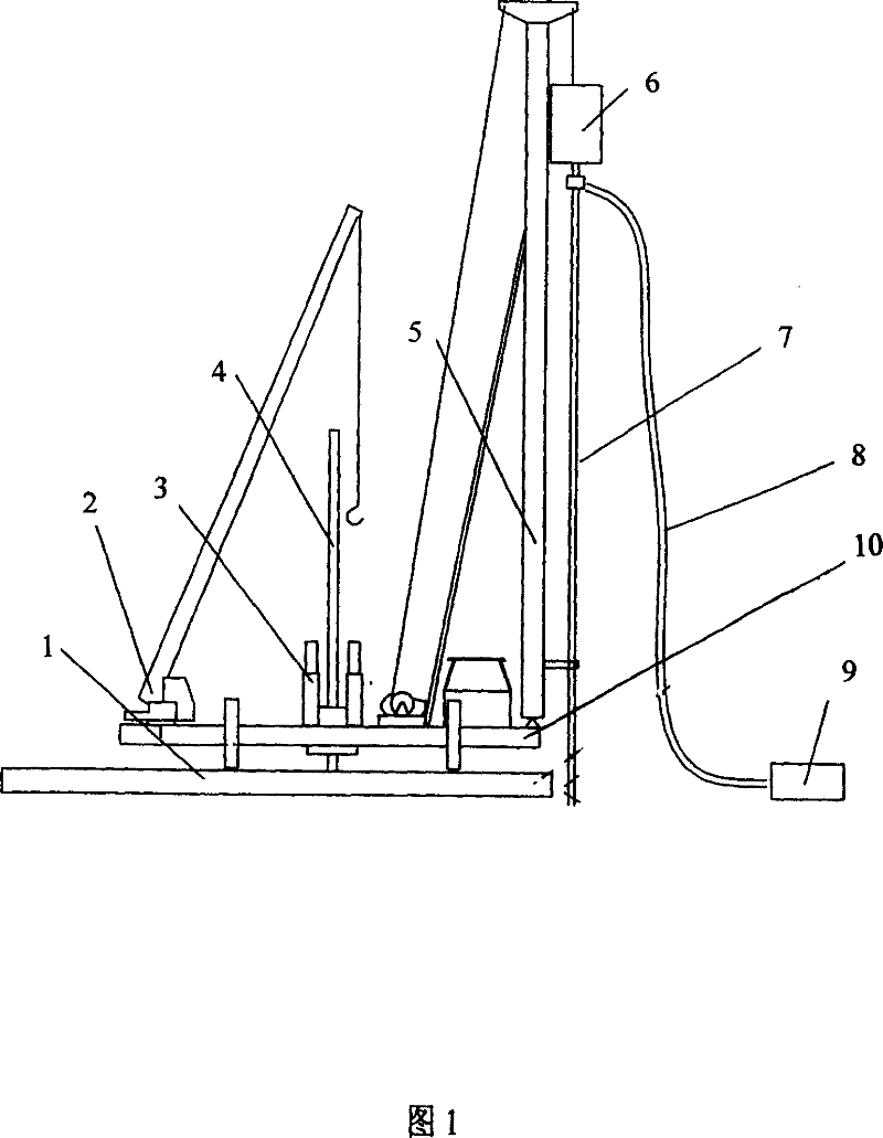
[0027] As shown in Figure 1, the situation that the mixing pile construction mechanism of the present invention is combined with the holding pressure type static pressure pile construction mechanism: the mast 5 of the mixing pile mechanism, the power head 6 of the mixing pile construction mechanism, the drill of the mixing pile construction mechanism The mixing pile construction mechanism composed of the rod 7 and the holding pressure pile construction mechanism composed of the auxiliary crane 2 and the holding pressure pile pressing mechanism 3 are installed together on the chassis of the pile machine that can slide on the main walking slideway 1 of the hydraulic walking mechanism 10 on.
[0028] During specific construction, the drill pipe 7 of the mixing pile construction mechanism is first aligned with the pile position, and the main walking slideway 1 of the hydraulic stepping mechanism is walked to the right side of the pile driver, and the power head 6 of the mixing pile...
Embodiment 2
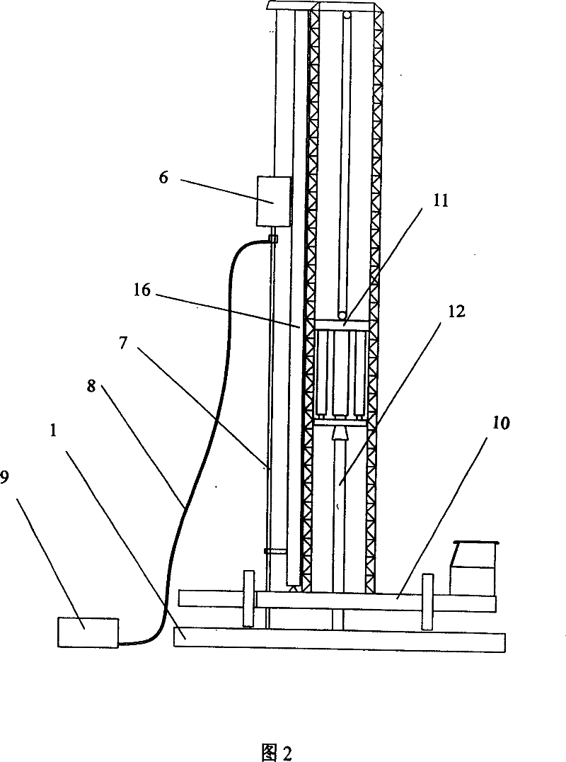
[0030] As shown in Figure 2, the situation of the combination of the mixing pile construction mechanism of the present invention and the top pressure type static pressure pile construction mechanism: the drill pipe 7 of the mixing pile construction mechanism, the power head 6 of the mixing pile construction mechanism, and the combination of the stirring and pressing pile The mixing pile construction mechanism composed of the frame 16, the top pressure pile pressing mechanism 11 and the top pressure pile pressing mechanism composed of the mixing and pressing pile combination frame 16 are installed together on the main walking slideway 1 of the hydraulic walking mechanism. On the pile driver chassis 10 of sliding.
[0031] During specific construction, the drill pipe 7 of the mixing pile construction mechanism is first aligned with the pile position, and the main walking slideway 1 of the hydraulic stepping mechanism is walked to the left side of the pile driver chassis 10, and t...
Embodiment 3
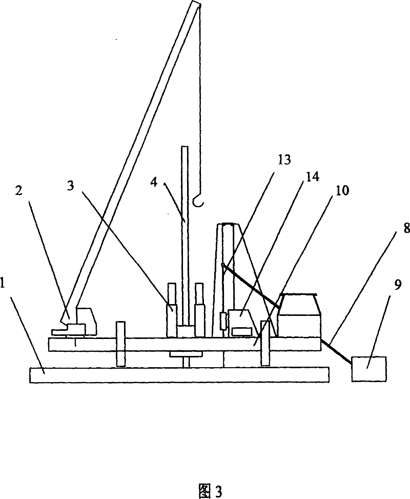
[0033] As shown in Figure 3, the situation that the high-pressure jet grouting pile construction mechanism of the present invention is combined with the pressure pile construction mechanism: the high-pressure jet jet pile composed of the drill pipe 13 of the jet jet pile construction mechanism and the main engine 14 of the jet jet pile construction mechanism The construction mechanism is jointly installed on the pile driver chassis 10 that can slide on the main walking slideway 1 of the hydraulic stepping mechanism with the self-contained auxiliary crane 2 and the holding pressure pile construction mechanism 3 composed of the holding pressure pile pressing mechanism 3.
[0034] During the specific construction, the drill pipe 13 of the rotary grouting pile construction mechanism is first aligned with the pile position, and the main walking slideway 1 of the hydraulic stepping mechanism is walked to the right side of the pile driver, and the main machine 14 of the rotary grouting...
PUM
 Abstract
Description
Claims
Application Information
 - R&D
- Intellectual Property
- Life Sciences
- Materials
- Tech Scout
- Unparalleled Data Quality
- Higher Quality Content
- 60% Fewer Hallucinations
Browse by: Latest US Patents, China's latest patents, Technical Efficacy Thesaurus, Application Domain, Technology Topic, Popular Technical Reports.
© 2025 PatSnap. All rights reserved.Legal|Privacy policy|Modern Slavery Act Transparency Statement|Sitemap|About US| Contact US: help@patsnap.com


