Microwave oven

A technology for a microwave oven and a bottom plate is applied in the field of microwave ovens, and can solve the problems of reduced performance of microwave ovens and the like

Inactive Publication Date: 2008-01-09
LG ELECTRONICS (TIANJIN) APPLIANCES CO LTD
View PDF5 Cites 0 Cited by
  • Summary
  • Abstract
  • Description
  • Claims
  • Application Information

AI Technical Summary

Problems solved by technology

Even so, there is no structure for cooling the above-mentioned fan motor 18b in the microwave oven, so there is a problem that the performance of the microwave oven decreases due to overheating of the above-mentioned fan motor 18b.

Method used


Image

  • Microwave oven
  • Microwave oven
  • Microwave oven

Examples


Embodiment Construction

[0059] Various embodiments of the heat dissipation structure of the microwave oven according to the present invention will be specifically described below with reference to FIGS. 6 to 12 .

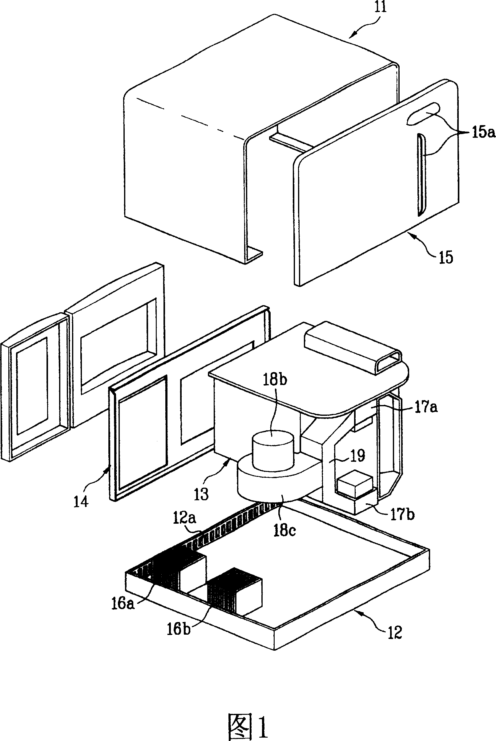
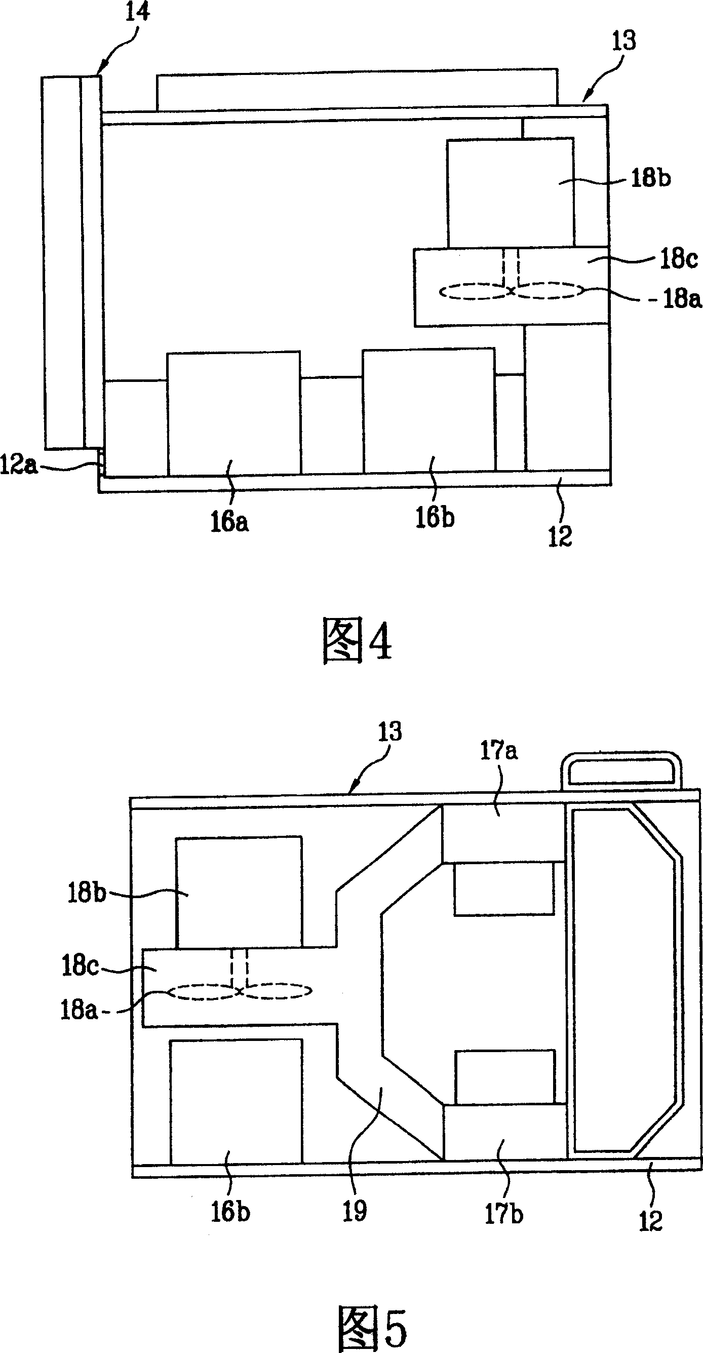
[0060] At first, adopt the first embodiment of the microwave oven of the present invention as shown in Figure 6, generally comprise the following parts, namely: shell 110, bottom plate 120, cavity 130, front panel 140, rear panel 150, a pair of transformers 161,162, A pair of magnetrons 171 , 172 , a blower fan 181 , a fan motor 182 , a fan cover 183 and an air duct 190 .

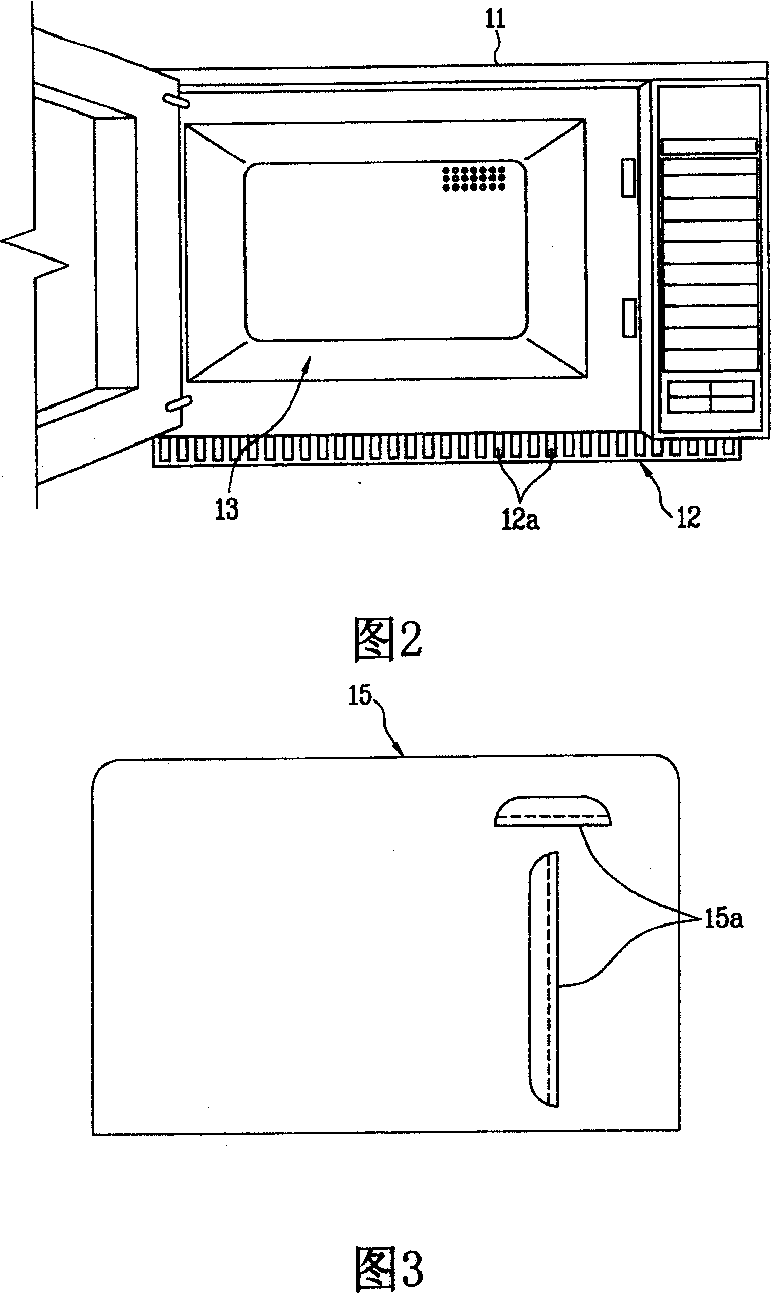
[0061] The shell 110 forms the two sides and the top of the microwave oven, and the bottom plate 120 , the front panel 140 and the rear panel 150 are respectively connected to the top of the shell 110 .

[0062] In addition, the bottom plate 120 forms the bottom surface of the microwave oven, on which a cavity 130 is disposed, and an electric control room is formed on one side of the cavity 130 .

[0063] Here, various...


PUM


Abstract

The microwave oven of the present invention has length reduced via altering the arrangement of electric parts and effective cooling to various electric parts. It consists of casing, chassis, cavity, front panel, back panel; the first transformer in the front part on the chassis and the second transformer in the back part on the chassis; the first magnetron in the upper part beside the cavity and between two transformers and the second magnetron in the lower part beside the cavity and between two transformers; blowing fan and its motor in the space of the second transformer; fan hood to protect the fan; ventilating pipe communicated with the fan hood to guide air flow to the magnetrons.

Description

technical field [0001] The present invention relates to a microwave oven, more specifically to a heat dissipation structure of a microwave oven for dissipating heat from each component of the microwave oven. Background technique [0002] In general, a microwave oven (MWO: microwave oven) uses high-frequency waves (2,450 MHz per second) as a heating source to cook food using intermolecular frictional heat generated by disturbing the molecular arrangement of food. [0003] Such a microwave oven mainly includes a type having a single magnetron and a type including a plurality of magnetrons. [0004] The above-mentioned microwave ovens equipped with a single magnetron are mainly used in households where microwave ovens are not frequently used, and the microwave ovens equipped with multiple magnetrons are mainly used in businesses or convenience stores where microwave ovens are frequently used. [0005] 1 to 5 schematically show the internal structure of a microwave oven equippe...

Claims


Application Information

Patent Timeline
Patent Type & Authority Patents(China)
IPC IPC(8): F24C7/02H05B6/64H05B6/80
Inventor 李东宪金亮卿李尚律金完秀
Owner LG ELECTRONICS (TIANJIN) APPLIANCES CO LTD
Why Eureka
Try Eureka