
Cable core current detector

A cable core and detector technology, applied in voltage/current isolation, measuring current/voltage, instruments, etc., can solve the problem of not easy to measure cable current signal, etc., and achieve excellent parameter performance, compact structure and wide measurement range. Effect

Inactive Publication Date: 2008-02-20
NORTHWEST INST OF NUCLEAR TECH
View PDF7 Cites 0 Cited by
  • Summary
  • Abstract
  • Description
  • Claims
  • Application Information

AI Technical Summary

Problems solved by technology

[0002] In scientific research and practical work, sometimes it is necessary to measure the current in the core wire of the cable connected to the circuit. At present, the commonly used method is to strip the outer shielding layer of the cable, or use a lead wire to lead the core wire current to Come out, and then use the detector to measure; but for the case where the cable adapter is welded at both ends and installed in the device, it is not easy to measure the current signal in the cable

Method used


Image

  • Cable core current detector
  • Cable core current detector
  • Cable core current detector

Examples


specific Embodiment

[0023] The parameter of detector among the present invention is:

[0024] w=0.01m; r 2 = 0.023 meters; r 1 = 0.01 meters; n = 15 circles; u r = 2000; u 0 =4π×10 -7 . From the inductance formula: L = w u 0 u r n 2 2 π ln ( r 2 / r 1 )

[0025] Get: L=7.496×10 -4 h

[0026] The above parameters w coil width, r 1 is the outer diameter of the coil, r 2 is the inner diameter of the coil, n is the number of turns of the coil, u r is the relative permeability, u 0 is the vacuum permeability;

[0027] It is easy to satisfy the condition of wL>>R, so the measured signal in this detecto...


PUM


Abstract

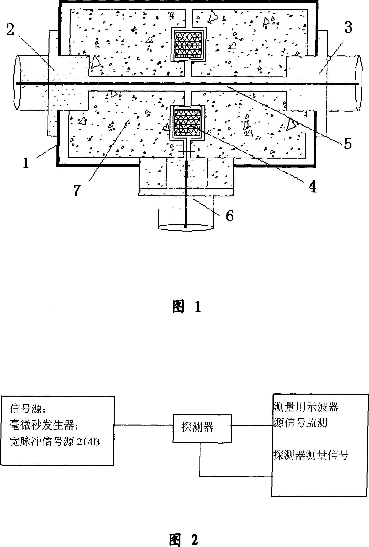
A detector is designed in cylinder shape-embedded structure as its axial centre is central conduction wire, its two ends are connected to standard cable switching seat internal core, its outer layer is metal shielded shell connected to outer shell of cable seat, measurement signal of the detector is at middle position and the signal is led out by standard cable seat in horizontal direction.

Description

1. Technical field: [0001] The invention relates to a cable core wire current detector; in particular, it is a non-contact pulse current detector capable of real-time and dynamic measurement of the cable core wire current. 2. Background technology: [0002] In scientific research and practical work, sometimes it is necessary to measure the current in the core wire of the cable connected to the circuit. At present, the commonly used method is to strip the outer shielding layer of the cable, or use a lead wire to lead the core wire current to Come out, and then use the detector to measure; but for the case where the cable adapter is welded at both ends and installed in the device, it is not easy to measure the current signal in the cable. 3. Contents of the invention: [0003] The object of the present invention is to provide a cable core wire current detector which is convenient to use and accurate in measurement. [0004] In order to achieve the above object, the technica...

Claims


Application Information

Patent Timeline
Patent Type & Authority Patents(China)
IPC IPC(8): G01R19/00G01R15/18
Inventor 李宝忠
Owner NORTHWEST INST OF NUCLEAR TECH
Learn More