
Communication equipment and its internal link fault positioning method

A technology for communication equipment and link faults, applied in the field of communication, can solve the problems of inability to judge whether inter-board communication is reliable, difficult on-line analysis of inter-board communication faults and remote fault location, etc., to reduce incomplete results and accurate communication Reliability, Avoidance, and High Level Effects

Inactive Publication Date: 2008-02-20
HUAWEI TECH CO LTD
View PDF4 Cites 2 Cited by
  • Summary
  • Abstract
  • Description
  • Claims
  • Application Information

AI Technical Summary

Problems solved by technology

[0006] The invention provides a communication device and a method for locating its internal link faults, so as to solve the problems in the prior art that it is difficult to perform online analysis and remote fault location on the internal inter-board communication faults of the device, and it is impossible to judge whether the inter-board communication is reliable

Method used


Image

  • Communication equipment and its internal link fault positioning method
  • Communication equipment and its internal link fault positioning method

Examples


Embodiment Construction

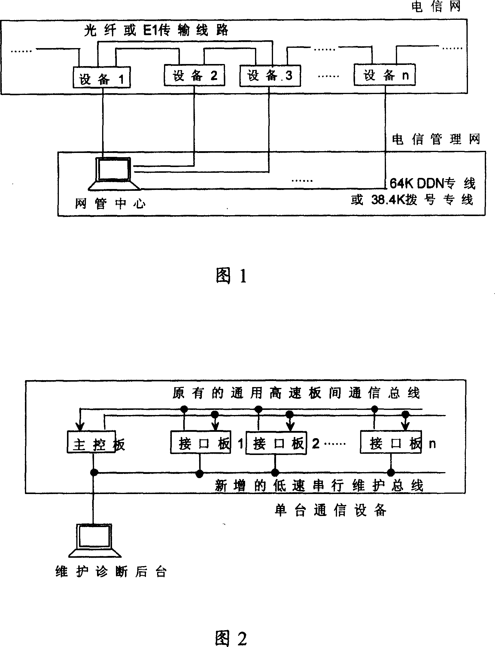
[0026] In order to realize online analysis and remote positioning of internal communication interruption faults of the equipment, the core of the present invention is to set an "inter-board communication bus + maintenance bus" structure inside the equipment.

[0027] As shown in Figure 2, a single communication device includes: a main control board, a plurality of single boards, a communication bus connecting the main control board and each single board, and a maintenance bus. background) connection. The maintenance and diagnosis console can also be connected to the maintenance bus through a standard interface, such as an Ethernet port, which is converted into a maintenance bus by special components. There may be multiple communication devices, and each communication device is connected to the maintenance and diagnosis station through the maintenance bus, thus forming a communication system. The maintenance bus provides the physical connection between the single board, the ma...


PUM


Abstract

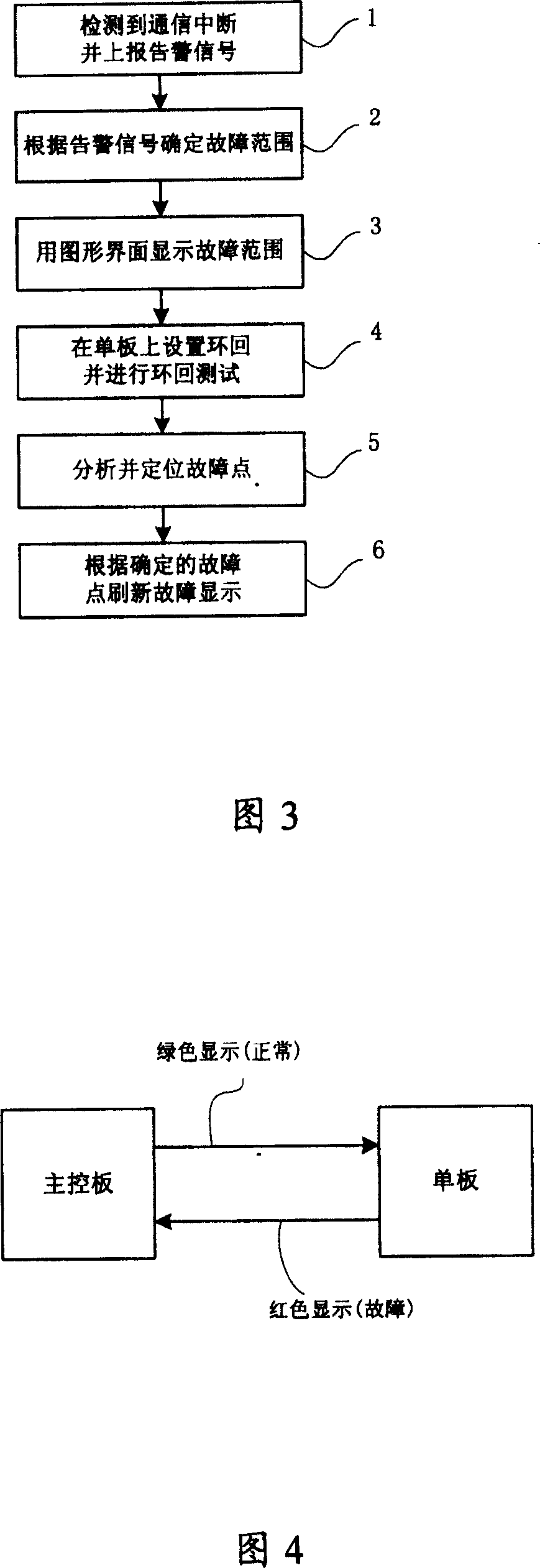
The invention discloses a communication system and location method for its inner communication fault to overcome the problems of hard online analysis, remote fault location and can not deciding whether the interboard communication reliable. The method comprises: detecting whether the interboard communication interrupted, if yes, using maintenance bus to report alarm signal to maintenance diagnosis platform; determining fault range by the said platform to set opposite level loops on alarm single board and near board by maintenance bus and command single board to send and receive message to complete loop test on interboard communication channel; then, releasing the loops, and determining the fault point according to loop test result.

Description

technical field [0001] The invention relates to a fault processing technology in the field of communication, in particular to a fault location method of a communication device and its internal link. Background technique [0002] Communication networks have changed dramatically over the past few years. Take the transmission network as an example. In the past, each communication line was only used to transmit a single channel, but after using the optical fiber system, many channels are multiplexed into a single transmission line, and the transmission rate is improved at the same time. Along with this, communication devices are becoming more and more complex. In order to cope with the huge traffic, high-speed communication channels must be provided between the boards in the communication equipment. From the outside of the equipment, the communication equipment does not seem to have changed much. It is still the frame and rack structure of "main control board + single board". ...

Claims


Application Information

Patent Timeline
Patent Type & Authority Patents(China)
IPC IPC(8): H04L12/24
Inventor 毛晓磊
Owner HUAWEI TECH CO LTD
Learn More