Valve assembly for hermetic compressor

A compressor and hermetic technology, applied in variable capacity pump components, liquid variable capacity machines, pump components, etc., can solve the problems of increased production cost and production time, complex structure of valve components, and reduced discharge efficiency

Inactive Publication Date: 2008-05-07
LG ELECTRONICS INC
View PDF9 Cites 0 Cited by
  • Summary
  • Abstract
  • Description
  • Claims
  • Application Information

AI Technical Summary

Problems solved by technology

[0009] However, in the conventional valve assembly, since it is necessary to additionally install a valve spring, a stopper, etc. in addition to basic constituent parts such as a cylinder head, a suction / discharge valve, and a top cover, the structure of the valve assembly is due to many components. parts and become complicated
[0010] Furthermore, in the conventional valve assembly, since an additional process is required to form the groove around the cylinder head discharge hole, production cost and production time are increased, and production efficiency is reduced
[0011] Furthermore, in the conventional valve assembly, the discharge valve is fixed to the cylinder head with the valve spring through a stopper etc., and a groove for inserting the valve, valve spring and stopper etc. is formed at the cylinder head because of consideration Due to the convenience of assembly and manufacturing errors, each component part needs to be manufactured with a certain tolerance. When the discharge of fluid is performed instantaneously under the condition of high discharge pressure, the discharge valve may be difficult to work accurately, thereby reducing the discharge efficiency.
[0012] In addition, when a momentary high pressure is generated during the discharge of refrigerant, the discharge valve may sequentially collide with the valve spring, stopper, etc., thereby generating noise

Method used


Image

  • Valve assembly for hermetic compressor
  • Valve assembly for hermetic compressor
  • Valve assembly for hermetic compressor

Examples


Embodiment Construction

[0045] Hereinafter, a valve assembly for a hermetic compressor according to the present invention will be described in detail with reference to the accompanying drawings.

[0046]While the present invention is capable of many embodiments, preferred embodiments are described below.

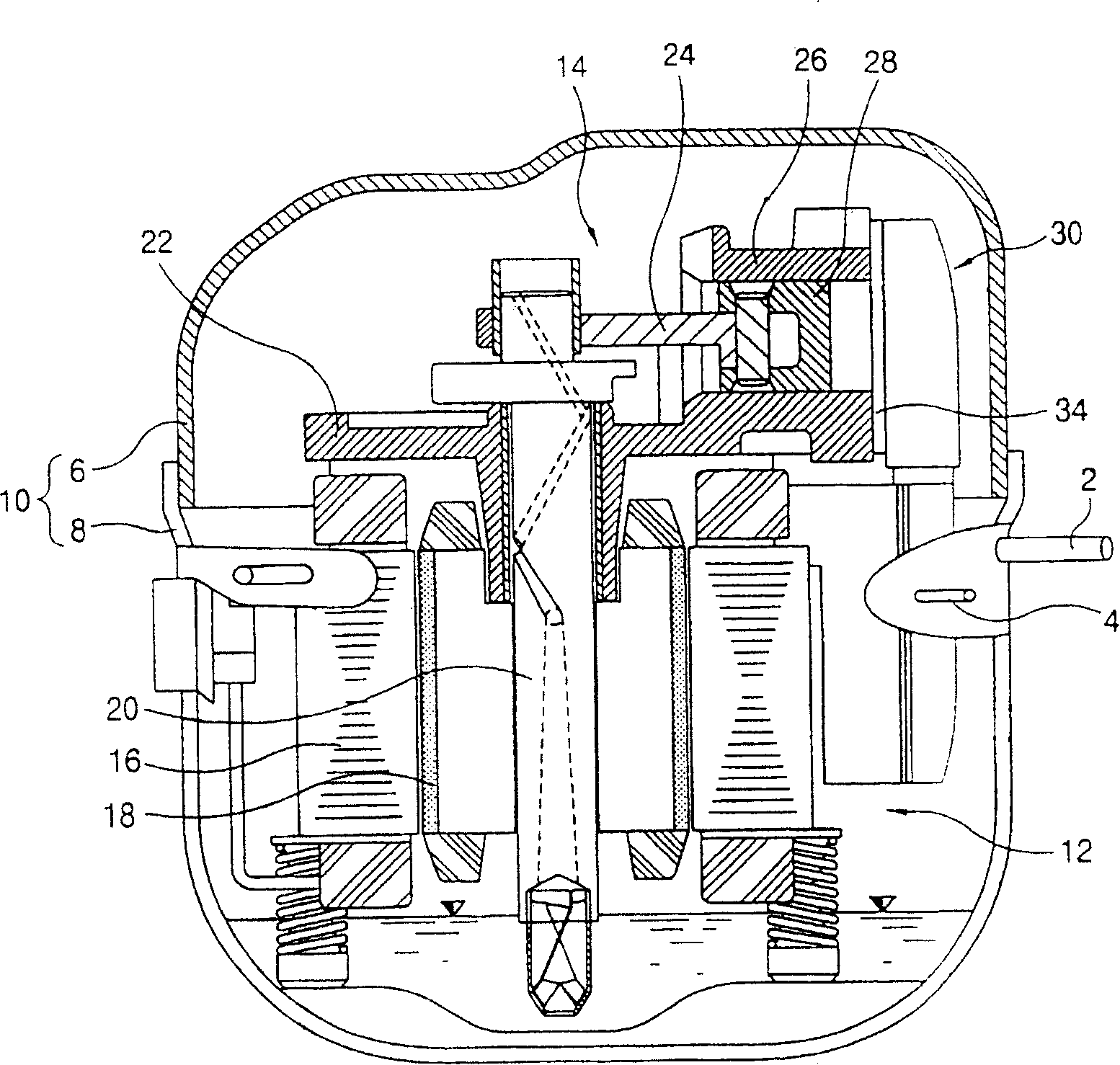
[0047] figure 1 is a cross-sectional view showing a hermetic compressor according to the present invention.

[0048] The hermetic compressor according to the present invention includes: a closed casing 10, where the suction pipe 2 and the discharge pipe 4 are respectively connected; a driving part 12, which is installed in a lower part of the casing 10, and generates rotational force; and a compression part 14 , which is arranged at the upper portion of the casing 10 , compresses the fluid sucked into the suction pipe 2 and discharges the fluid to the discharge pipe 4 using the rotational force generated by the driving part 12 .

[0049] In the case 10, the upper case 6 and the lower case 8 are c...


PUM


Abstract

A valve assembly (30) for a hermetic compressor in accordance with the present invention includes a cylinder head (34) installed to an opened end of a cylinder (26) having a specific space filled with a fluid and having a suction hole (48) and a discharge hole (50), a suction valve (36) fixed to a certain surface of the cylinder head (34) and opening / closing the suction hole (48), a discharge valve (38) fixed to the other surface of the cylinder head (34) and opening / closing the discharge hole (50) and a head cover (40) fixed to the surface of the cylinder head (34) and having a suction space (42) at which a fluid is sucked and a discharge space (44) at which a fluid is discharged.

Description

technical field [0001] The present invention relates to a hermetic compressor, and more particularly, to a valve assembly for the hermetic compressor, which can simplify the structure of the compressor and improve compression efficiency. Background technique [0002] Generally, compressors can be classified into several types according to the type of compression, and hermetic compressors are mainly used in air conditioners that require downsizing and weight reduction. [0003] The hermetic compressor is composed of a closed casing, a driving part, and a compression part. The driving part is accommodated in the casing and generates driving force. The compression part compresses the fluid using the rotational force generated by the driving part. [0004] The compression part includes: a cylinder into which fluid flows; a piston accommodated in the cylinder so as to perform reciprocating motion; a valve assembly, etc., which supply fluid to the cylinder and discharge compressed...

Claims


Application Information

Patent Timeline
Patent Type & Authority Patents(China)
IPC IPC(8): F04B39/10F04B39/00
CPCF04B39/1073Y10T137/7892Y10T137/7891F04B39/00F16K15/162F16K15/16
Inventor 赵宰皓
Owner LG ELECTRONICS INC
Why Eureka
Try Eureka