Eureka AIR delivers breakthrough ideas for toughest innovation challenges, trusted by R&D personnel around the world.

Safety power supply device of set battery

A power supply device and battery technology, which is applied to battery pack components, secondary battery repair/maintenance, circuits, etc., can solve the maintenance and management loopholes of collective batteries, cannot stack multiple collective batteries, and cannot directly visually observe the single battery. Problems such as abnormal appearance of a secondary battery

Active Publication Date: 2013-12-11
BIXIANG ELECTRIC ENERGY HIGH SCI & TECHCO
View PDF1 Cites 0 Cited by
  • Summary
  • Abstract
  • Description
  • Claims
  • Application Information

AI Technical Summary

Problems solved by technology

[0006] First, when a plurality of assembled batteries are to be stacked and electrically connected, the conductive strips exposed on the two sides outside the frame will not only cause a high risk of contact short circuit between the conductive strips between different assembled batteries, but also the known frame is almost impossible Direct stacking of multiple collection batteries
[0007] Second, each of the above-mentioned single secondary batteries is installed on the inner surface of the fuse in a shielded manner. Sometimes the failure of a single secondary battery is leakage or swelling and bursting but the fuse is not broken. The above-mentioned known structure cannot be directly seen The abnormal appearance of a single secondary battery was observed, and the battery and fuse had to be disassembled to be taken out for inspection. The above-mentioned structure was not convenient for visual maintenance, which led to loopholes in the maintenance and management of assembled batteries

Method used


Image

  • Safety power supply device of set battery
  • Safety power supply device of set battery
  • Safety power supply device of set battery

Examples


Embodiment Construction

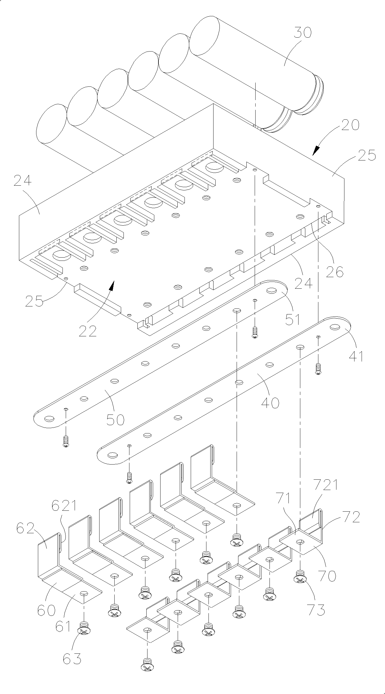
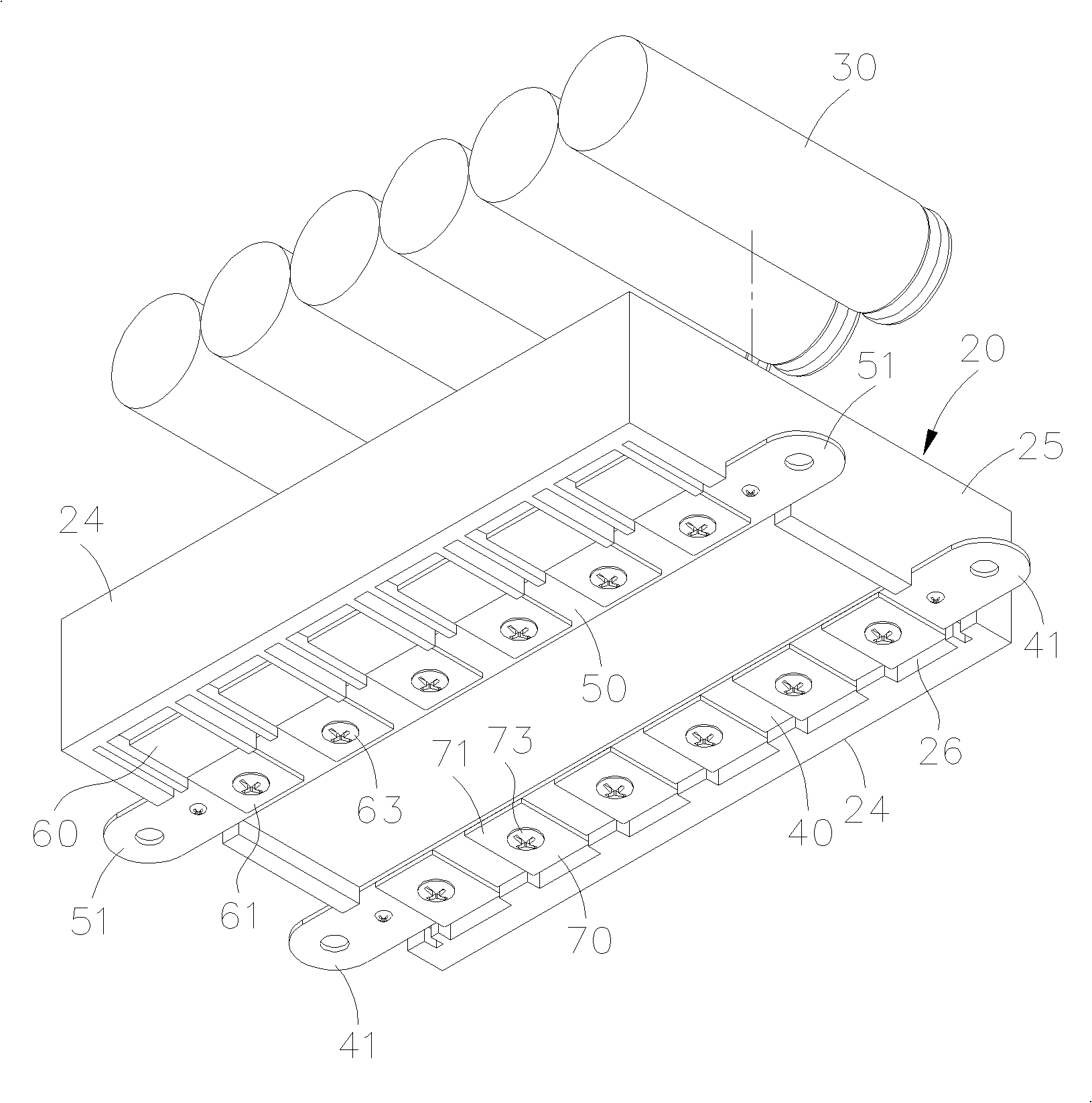
[0042] First, please refer to figure 2 , 3 As shown in and 4, a safety power supply device for an assembled battery provided by an embodiment of the present invention is mainly provided with a plurality of single secondary batteries on one side of a frame, and a positive electrode is installed on the other side of the frame Conductive strips, a negative conductive strip and multiple fuses, each single secondary battery is connected to the positive and negative conductive strips through multiple connectors and fuses, so that each single secondary battery is individually connected to a fuse , thus forming a collection battery.

[0043] Its specific structure is: the frame 20, the corresponding two sides are respectively formed into a housing groove 21 and a set of surface 22, the housing tank 21 is a quadrilateral structure with four side frames, and the housing tank 21 The back side of the bottom 23 is the aforementioned assembling surface 22, wherein, the two sides correspo...


PUM


Abstract

The invention discloses a safety power supply device of a set battery. The safety power supply device is characterized in that a plurality of single secondary batteries are arranged on one surface of a frame while an anode conductive strip, a cathode conductive strip and a plurality of fuses are arranged on the other surface of the frame; each single secondary battery is connected with the anode and cathode conductive strips through a plurality of connecting pieces and the fuses so that each single secondary battery is individually connected with one fuse, therefore, a set battery is formed; each single secondary battery is on one surface of the frame; each fuse and the anode and cathode conductive strips are arranged at intervals on the other surface of the frame, therefore, the device is beneficial to assembling, maintaining and overhauling components; furthermore, the device is beneficial to safely stacking or connecting a plurality of set battery devices in the invention in an abutting manner.

Description

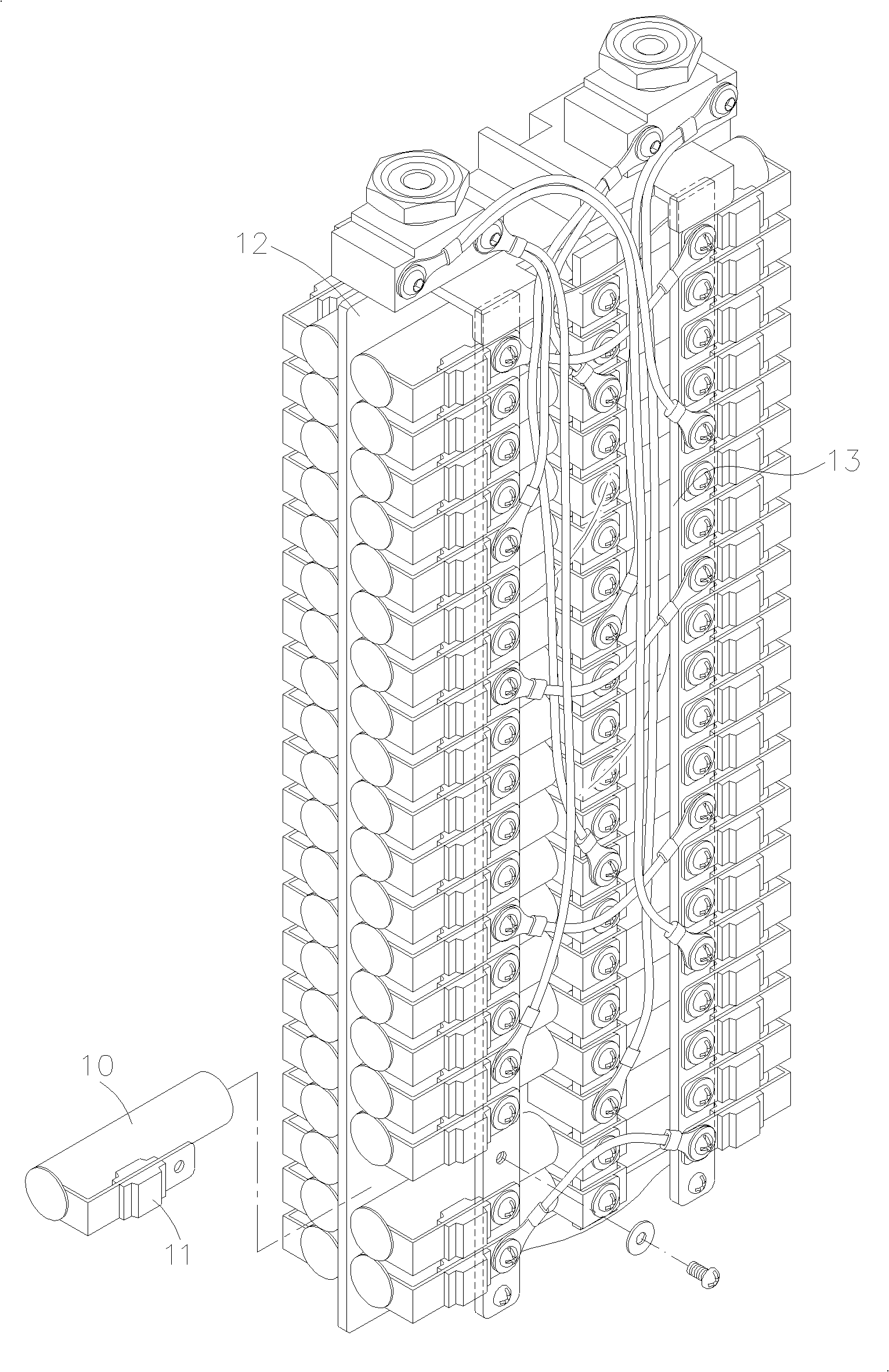
technical field [0001] The invention relates to a safety power supply device for an assembled battery, in particular to an assembled battery structure formed by connecting a plurality of single secondary batteries. Background technique [0002] figure 1 Shown is the structure previously invented by the applicant (US Patent No. US7670718), which mainly installs a plurality of single secondary batteries 10 and a corresponding number of individual fuses 11 outside a special I-shaped frame 12 And constitute a set of batteries. [0003] One side of each single secondary battery 10 is welded with a single fuse 11 respectively, and then the electric power of each single secondary battery 10 is connected in series or in parallel through a plurality of conductive strips 13 and then collected and outputted. [0004] When any single secondary battery fails and causes the passing current value to exceed the rated value, the individual fuse directly connected to the faulty single secon...

Claims


Application Information

Patent Timeline
Patent Type & Authority Patents(China)
IPC IPC(8): H01M10/42H01M2/10H01M2/34H01M2/20
CPCY02E60/12Y02E60/10
Inventor 伍必翔
Owner BIXIANG ELECTRIC ENERGY HIGH SCI & TECHCO
Why Eureka
Eureka Blog
Learn More