Magnetic induction assembly and manufacturing method thereof

A technology of magnetic induction components and manufacturing methods, applied in the direction of inductance/transformer/magnet manufacturing, coil manufacturing, transformer/inductor parts, etc., can solve the problems of product difficulty in price competition, transformer damage, increased burden, etc.

Active Publication Date: 2019-11-12
LINKCOM MFG +1
View PDF15 Cites 0 Cited by
  • Summary
  • Abstract
  • Description
  • Claims
  • Application Information

AI Technical Summary

Problems solved by technology

[0005] 1. It should be noted that using PCB manufacturing technology to print conductive coil patterns to produce primary and secondary coils including transformers is complicated, and the cost burden is high. It is difficult for the manufactured products to have a price competitive advantage in the market.
[0006] 2. Coating insulating varnish on the surface of the two sets of coils to isolate each other is difficult to meet the safety requirements of transformer manufacturing, and it is easy to cause damage to the transformer during operation; especially for AC-DC transformers used to connect to the mains, due to The voltage difference at the AC power supply terminal is large, and the isolation between the primary coil and the secondary coil must have a certain safety distance in terms of specifications.
[0007] 3. For the transformer disclosed in the previous technology 1, when a set of primary coils and two sets of secondary coils are assembled with the iron core, the central magnetic guide column of the iron core must pass through the assembly holes reserved on each set of coils, so these coils are assembled The alignment of the holes must be very precise, otherwise it will cause difficulties in assembly; especially the three sets of coils are independent units and components, which must be threaded on the iron core separately during the manufacturing process. The process is not only complicated and wastes manpower, but also The required precision is high, otherwise it will easily lead to an increase in the failure rate of assembly, or cause the problem that the gap between the coil and the core is too large
In particular, the two sets of secondary coils made of PCB have to accurately connect the coil patterns of each other through the conductive

Method used


Image

  • Magnetic induction assembly and manufacturing method thereof
  • Magnetic induction assembly and manufacturing method thereof
  • Magnetic induction assembly and manufacturing method thereof

Examples


Embodiment Construction

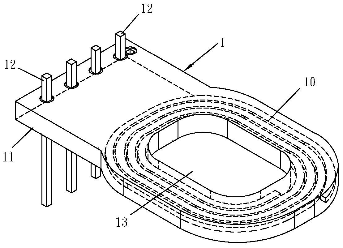
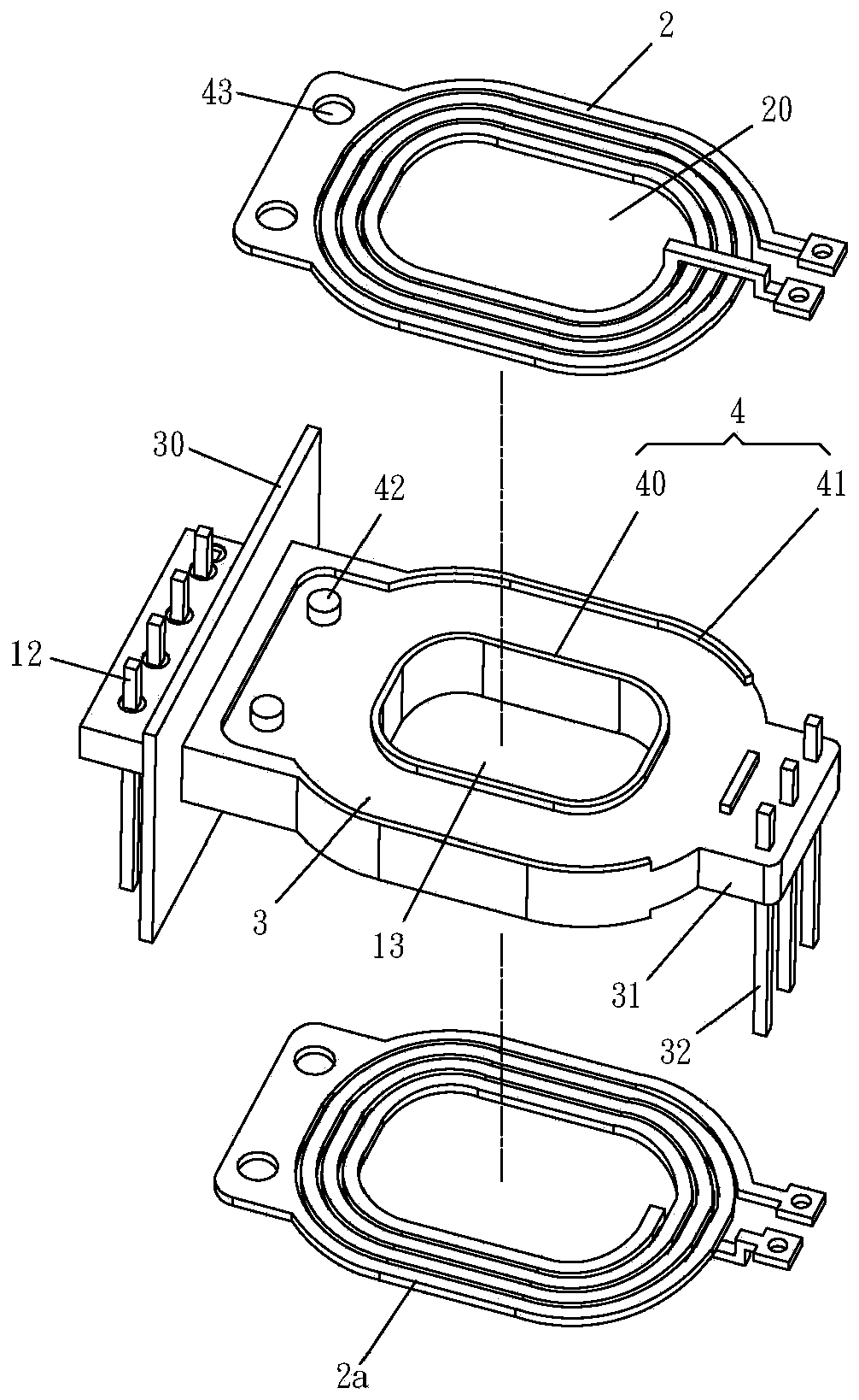
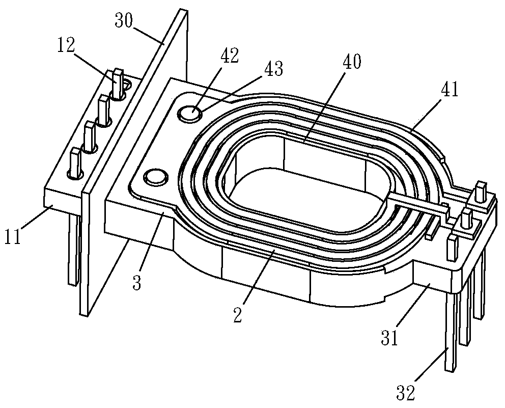
[0032] The present invention relates to a magnetic induction component and its manufacturing method. For the manufacturing method and steps, please refer to Figure 1 to Figure 6 What was revealed mainly included:

[0033] Step 1, such as figure 1 As shown, a conductive pattern 10 is arranged on a PCB11 to form a first group of coils 1 through a printed circuit board (hereinafter referred to as PCB) manufacturing technology. Preferably, the PCB11 is a multilayer printed circuit board. The conductive pattern 10 can be arranged in the interlayer of the multi-layer PCB 11, so that the distance between the conductive pattern 10 and the outside is increased; in addition, several first conductive pins 12 can be pre-arranged on the PCB 11, through which several first conductive pins 12 can be in contact with the conductive pattern 10 and conduct with the external circuit;

[0034]Step 2, using a conductive material to form a flat (or called planar) second group of coils 2 by moldin...


PUM


Abstract

The invention discloses a magnetic induction assembly and a manufacturing method thereof. The manufacturing method of the magnetic induction assembly comprises the following steps: arranging a conductive pattern on a printed circuit board to manufacture a first group of coils and establish a first adaptive hole; manufacturing at least one second group of coils by using a conductive material and establishing a second adaptive hole; coating the surface of the first group of coils without the first adaptive holes with a first isolation layer made of an insulating material, and establishing a positioning mechanism to provide alignment of the first adaptive holes and the second adaptive holes; an iron core with a magnetic conductive column is manufactured, and the magnetic conductive column isinserted into the first adaptive hole and the second adaptive hole, so that the iron core is coupled with the first group of coils and the second group of coils; therefore, the production process of the transformer can be easily introduced into automation, so that the efficiency can be improved, and the reject ratio of products can be reduced.

Description

technical field [0001] The invention relates to a transformer, in particular to a magnetic induction component of the transformer and a manufacturing method thereof. The magnetic induction component can be applied and connected to a power supply and a circuit terminal to provide voltage conversion. Background technique [0002] The main structure of the transformer includes two sets of independent coils (coils), the so-called primary coils and secondary coils, and a common core (core) for magnetic conduction. The coil ratio converts the voltage value. In addition, in practical applications, the transformer is usually built on an independent insulating base (base), which is pre-arranged with several conductive pins (pins) connected to the coil to form a transformer assembly, and through these conductive The pin is welded to the external circuit, so that the transformer assembly is connected to the external circuit, and at the same time, the base is used as isolation to preve...

Claims


Application Information

Patent Timeline
IPC IPC(8): H01F27/28H01F27/30H01F41/04H01F41/00
CPCH01F27/2804H01F27/2823H01F27/306H01F41/04H01F41/041H01F41/00
Inventor 梁景伟王诏禾姜维凯姚健勇
Owner LINKCOM MFG
Why Eureka
Try Eureka